One of the greatest achievements in the field of structural engineering has to be the advent of steel. While steel has been known to humans since antiquity, its use for building things has only been exploited for about 150 years or so. And in that time, steel has revolutionized the way we look at engineering problems. Taking advantage of its high strength to weight ratio, engineers have been able to span farther and build taller than ever before.

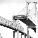
The first bridge to be built entirely from steel was the Eads Bridge in St. Louis in 1874. Besides being well known for this distinction, the bridge is notable for a host of other reasons including the use of the cantilever erection method and its massive foundations. The first bridge to use steel wire woven on site for a suspension bridge, in lieu of iron chain links, was the Brooklyn Bridge in New York in 1883. Both of these bridges paved the way for many more like them and in turn allowed humans to span larger distances than ever before. Spans previously seen as not bridgeable were now within reach with the use of this new wonder material.

But like any new invention, we continue to learn more about steel the more we use it. Early steels were primitive even when made using the best techniques of the day. Modern methods allow more control over the carbon content and thus more control over the quality of the material. This has allowed for higher strengths, more ductility, weldability and even corrosion resistance.
We have also learned about the limitations of steel over time and how to work around them. Because steel is so strong and so light weight, the amount of material necessary in a structure can often be minimized. By minimization, we often lose redundancy. This is particularly true in trusses, hence the rise of the term fracture critical. The loss of any member, because of a lack of redundancy, results in the collapse of the structure. Due to changes in economics and other factors, trusses are no longer commonly built. But in plate girder structures, where two girder lines would suffice you will often find three girder lines used to address redundancy concerns.
A fracture critical member is further defined in the bridge world to mean a tension member or portion of a member that is non-redundant. So why tension? For that, we have to talk about fatigue.
Fatigue is a tendency of metal alloys to fracture or fail at stresses below their yield point, usually due to cyclic stresses. It usually manifests itself when members are stressed in tension. The main purpose of a bridge is to convey transient or “live” loads across some span. The transient nature of the loads means that components experience some amount of cyclic stressing.
For example, in a single span bridge when a truck rolls across the structure, the beam carrying the load will experience a range of stress due to this truck. At midspan, the load will increase from zero to some maximum and back to zero as it crosses. The stress range is then the maximum stress less the initial or zero stress.
Now imagine that truck crossing the bridge thousands of times a day. And imagine that happening 365 days a year for many, many years. This is the number of cycles that the member experiences in its life going through that stress range.
In fatigue design, engineers will determine the expected fatigue stress range. By AASHTO design codes, this is the same HS-20 truck only with a 15% impact factor. This stress is a function of the load and the section properties of the element under consideration. Since the loading is dictated by code, the only way to reduce the stress range is to increase the size of the section.
Once the stress range is known, the allowable stress range is then calculated. This is a function of the number of cycles of load the element will experience over its expected life and a constant value that is related to design features of the element that can cause stress concentrations. Basically, this constant is a measure of how much more likely a particular design feature will affect the fatigue life.
In theory, there is a theoretical limit on stress – if the size of the section can be suitably large and the stress range suitably reduced below this limit, then the material may experience an infinite number of cycles and never see failure.
The stress concentration constant is related to different detail categories in steel codes. These list a variety of different scenarios based on experience and the corresponding category. In typical bridge practice, good detailing tends to eliminate undesirable fatigue categories which will increase the fatigue life of a component. But in some cases this is not possible and those components must be designed carefully.
One spot where steel is particularly susceptible to fatigue is at girder ends. Prior to the understanding of fatigue and how it manifests itself, many bridges were designed with little or no consideration of fatigue behavior. Detailing that was considered fine for strength loads is now known to be poor for fatigue loading. Truss floorsystems use stringers to support the deck and they must transmit this loading to the floorbeams, which transmit the load to the truss nodes.
Where the stringers frame into the floorbeams there is usually a simple shear connection – a gusset plate and a series of rivets or bolts. To prevent geometric conflict between the floorbeam flange and the stringer flange, a notch is usually made in the top corner of the stringer. Today, this corner would be coped with a large radius to prevent stress concentrations from initiating fatigue cracks. But many older bridges do not have a rounded cope and many begin to see fatigue cracks form at these locations.
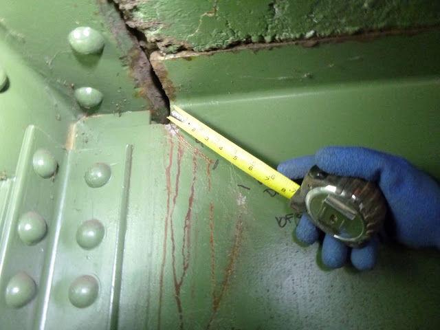
Often these cracks initiate but do not propagate – they don’t get worse. Bridge inspectors will monitor these cracks and if they get worse, a repair will usually be called for.
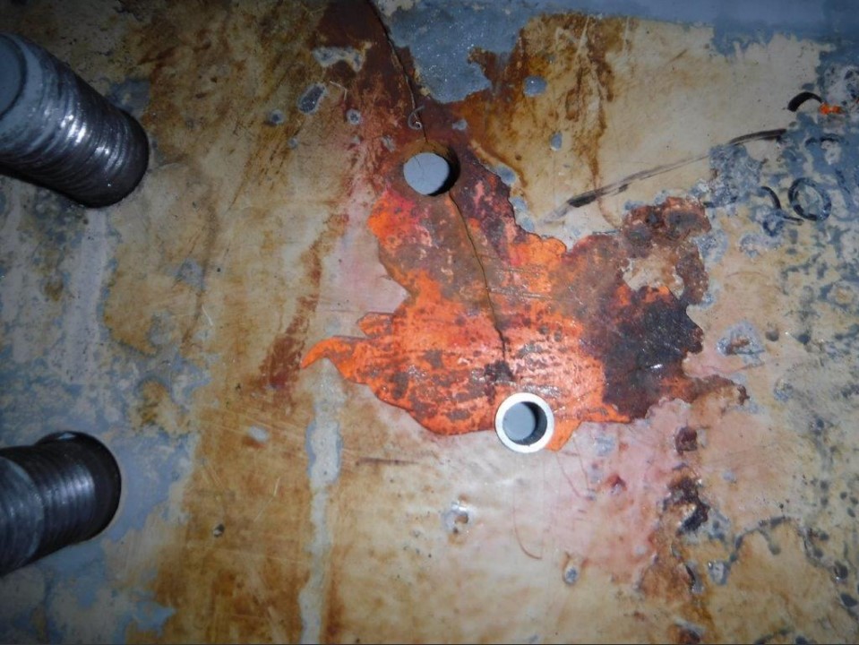
Cope cracks caused by fatigue can be corrected in a couple of different ways. The most common way is to locate the end of the crack using magnetic particle or dye penetrant tests (both forms of non-destructive testing). Once the end of the crack is located, a hole of about 1 to 1.5 inches in diameter is drilled. This helps eliminate the stress riser and typically stops continued crack propagation.
Another method is by using a StopCrackEx system. This method locates the end of the crack as described above, drilling a hole and installing a pressed in bushing into the hole. The bushing introduces residual compression to the surface around the hole. Since fatigue cracks are caused by residual tension, introducing compression in these areas can cancel out the stresses and prevent further propagation.
Care must be taken to properly diagnose the cause of cracking in stringers. Another mode for these cracks to occur is through out-of-plane bending. In the scenario above, loads which induce fatigue cracks are in-plane loads – that is loads applied vertically to the stringer, basically parallel to the plane of the web.
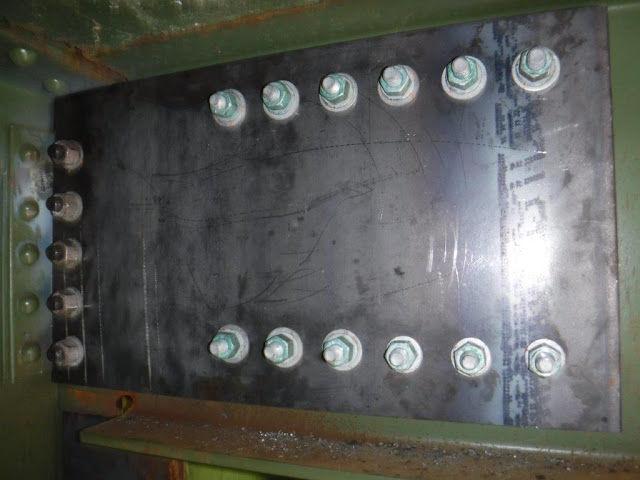
Where you see out of plane bending is where a diaphragm frames into a stringer via a simple shear connection. This shear connection is the problem as in reality it will also transmit moment. When moment is transmitted via simple shear connection, it tends to bend the web of the stringer in and out of plane – perpendicular to the web. After a number of cycles, this can often cause cracking to occur in the web. In these cases, installing bushings does nothing for the crack. The best remedy is to redesign the connection to engage the flanges of both elements in the transmission of moment. Drilling holes at the ends of the cracks will help arrest their growth and installing and torqueing a bolt into this hole can help introduce a little compression to the area.
We have come a long way since the days of the Eads Bridge in terms of our understanding of steel and its uses. And while there may not be a cure for fatigue, we have learned how to cope with its symptoms. In many cases we have eliminated fatigue problems for the life of a bridge. Yet in other elements, such as open grid decks and modular expansion joints, fatigue is a condition we just have to live with.
Views: 808