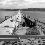
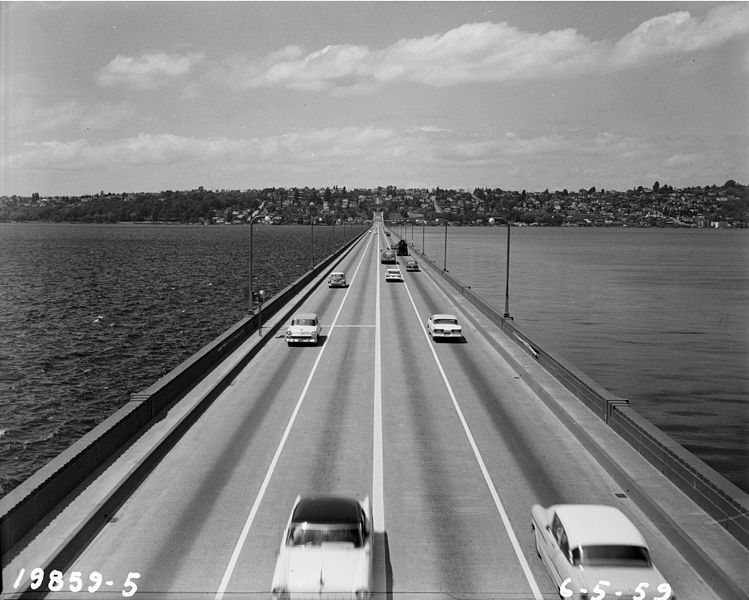
In this edition of The Bridge Guy, we pick up the story of the First Lake Washington Bridge on its tenth birthday. By now, the tolls have been removed from the bridge, ferry service across the lake has ended and traffic volumes quickly grow on the bridge. So popular is the bridge that a second lake crossing is contemplated as early as 1946. But, it would be another 17 years before the Second Lake Bridge would come to fruition and in the meantime Seattle’s population would grow by 26% between 1950 and 1960, while the population of the eastside of the lake grew by 88%. Demand for a second crossing was increasing!
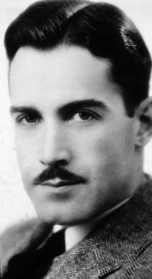
On June 30, 1967, the bridge was dedicated to the memory of Lacey V. Murrow, the Director of Washington State Highways when the bridge was built and brother of famous broadcaster Edward R. Murrow, by the Washington State Highway Commission.
Let’s take a look at some of the features of the bridge and get a feel for what it was like to maintain.
Under normal operation, the Army Corps of Engineers is charged with maintaining the water surface elevation in the Ship Canal between 20.0 feet and 22.0 feet. Beginning in mid-June each year, the Corps allows freshwater from the Canal to spill into Puget Sound, leveling off the Canal at 20.0 feet by December. This level is maintained until mid-February each year at which point the Corps begins to hold water at the Ballard Locks, filling the Canal and eventually leveling it off at 22.0 feet by late April.
Water level is lowered in the winter to allow for annual maintenance of docks and walls, to minimize wave erosion during storms and to provide storage space for high inflow during storms. Water level is raised in the summer to augment inflows for lock operations, saltwater return and fish passage. This predictable pattern has been in effect since 1917 when the Ballard Locks were first commissioned.
When engineers devised a floating bridge to cross Lake Washington, they needed to find a way to handle these elevation changes. As the lake level changes, so too does the bridge level. And since the bridge is moored to the bottom of the lake with anchor cables that are fixed in length, as the bridge moves up and down with the lake level the tension in these cables also changes.
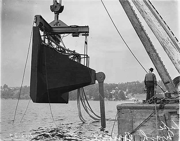
If the cable tensions are set at a mean tonnage at a certain water level, then as the bridge goes up with the lake – the tension in the cables increase. Conversely, as the bridge goes down with the lake – the tension in the cables decrease. This increase or decrease in tonnage is also related to the cable length. A longer cable is less stiff, meaning it takes more change in length to change the tension by a certain amount. Shorter cables are stiffer and are more sensitive to lake level changes.
Engineers developed an ingenious solution to this problem on the Murrow Bridge – free water ballast. A pumping system was devised that would pump water in and out of the bridge as the lake level changed, thereby changing the freeboard of the bridge. As the lake level went up, extra ballast water was pumped into the bridge – making it heavier. As the lake level went back down, this extra ballast water was pumped out – making it lighter. The idea was to regulate the ballast water such that the tension on the anchor cables was maintained at a constant level.
Though ingenious, the system was plagued by problems. The pumping system was unreliable – the pumps either got clogged up by flotsam in the water or the pumps just failed to operate. The entire system was difficult to maintain.
One engineer recalled his experience with the free water ballast system. Ballast cells were routinely inspected to check for the appropriate water level. Water levels that were higher or lower than expected usually indicated a faulty pump. One inspector climbed down the ladder into a ballast cell. His partner, confident that the water level in that cell was only a few inches deep, encouraged the young man to simply jump down into the cell and check the depth. As it was dark inside the cell (the bridge only had minimal lighting) the inspector could not verify his partner’s claim and took a leap of faith, literally. Instead of jumping into a few inches of water, he instead found himself immersed over his head in black, nasty ballast water. His partner then called out, my mistake – wrong cell! The young man would later recount, “…it was like the compactor scene from Star Wars.”
By the 1980’s, the pumping system on the bridge that regulated the ballast water levels inside the bridge had been abandoned. Water ballast was still in use on the bridge up to 1990, even though later vessel design codes, such as those maintained by Det Norsk Veritas (DNV), prohibited free water ballast on vessels as the sloshing effect can negatively impact the dynamic characteristics of the vessel. Without the pumping system to automatically regulate the anchor cable tension, the bridge maintenance crew began doing anchor cable adjustments manually – a practice that still continues to this day on all three of the Lake Washington floating bridges.
Anchor cable adjustment may be commonplace today on the lake bridges, but on the Murrow bridge they were an adventure. In those days, once the water pumps went away, only the short, stiff transverse cables near the ends of the bridge and the longitudinal cables needed regular adjustment. Without adjustment, at high lake levels the cables tend to become overloaded which limit their ability to absorb storm loading pulses without breaking wires. At low lake levels, insufficient tension meant that wind and wave action could knock the bridge out of alignment and overload the pontoons structurally.
A typical procedure for adjusting anchor cables would be as follows.
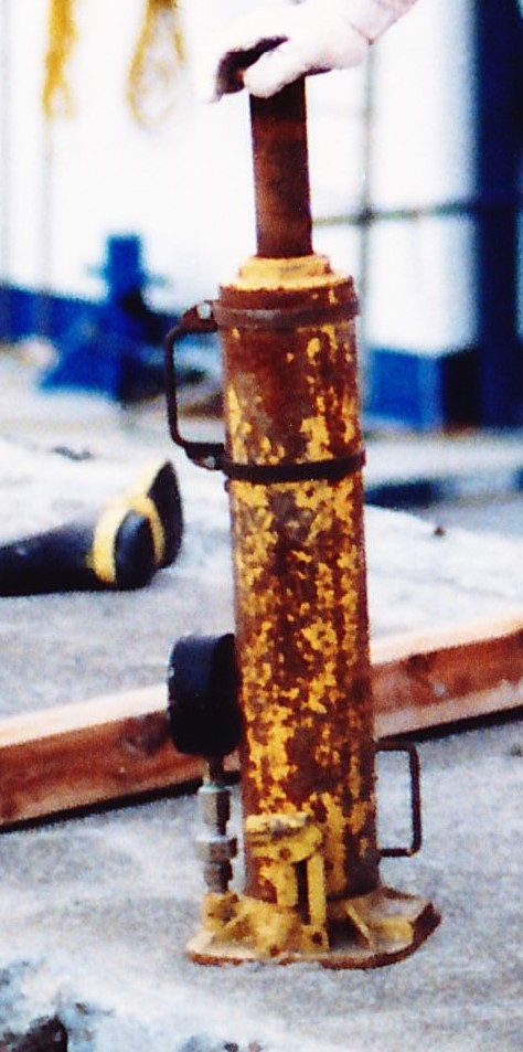
As there were no dedicated jacks in the cable ways for jacking cables, the crew would need to take the jacks with them from pontoon to pontoon. These were house jacks, like a large hydraulic bottle jack, not only heavy to carry but cumbersome to take down ladders.
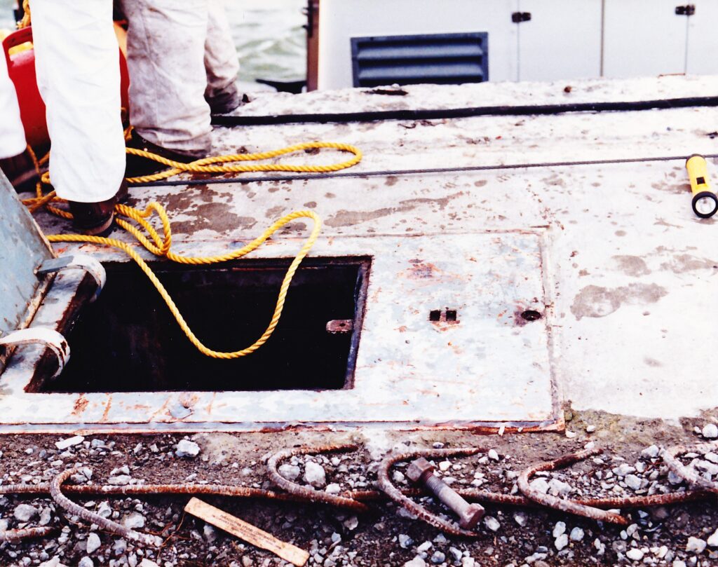
Hatches on the bridge were normally located at the anchor galleries with additional hatches located periodically along the pontoon. Hatches could be accessed in the sidewalk (only 4 feet wide) by walking down the length of the bridge or by boat. Incidentally, these sidewalks were swept with a 4 foot wide sweeper machine operated by a crew member. When a bag was full, it was left on the bridge rail and the bags were picked up later by pickup truck.
Once the hatch was opened, the crew was greeted by a dark, damp, musty cell and a steel ladder. Condensation was a serious problem on the bridge – after all, water was used to ballast the bridge. Years of dampness had taken its toll on the ladders. The ladders were originally attached at several points to the pontoon walls, however by the 1980’s most of these connections had corroded and broken. This meant a fun climb some 15 feet down into darkness, on a ladder only attached to the wall near the top.
Once on the bottom of the pontoon, you would walk across to another ladder and enjoy another fun climb up to the cable way. But once in position, the house jacks could be installed and manually cranked until the proper tension was achieved. Teamwork was required as two jacks needed to be cranked, one on each side of the cable. Cables are generally adjusted four times during the year, one large adjustment on the way up or down then a minor adjustment once the lake has leveled off to dial in the tonnage.
Catwalks along the cable ways were barely wide enough for two people to pass. In some spots, the crew would even use a single 2×6 board to cross between catwalks.
Darkness inside the bridge was enhanced by the black coated walls. This coating was likely some sort of tar, applied in a well-meaning attempt to waterproof the walls of the pontoons. To illuminate the anchor gallery, a single bare bulb fixture was provided. Spare light bulbs were always left in the cable ways and for good reason. Condensation had also taken its toll on the electrical systems on the bridge. Light bulbs routinely went bad inside the pontoons. More often than not, the light bulb would explode as it was turned on and another bulb would have to be installed.
All crew members carried what was called the “floating bridge tool kit.” This included a crescent wrench for opening hatches, pliers, screwdriver, putty knife and brush. This standard kit had everything the discerning crew member needed to maintain the bridge. Before closing a hatch, the gaskets would be brushed clean to make sure there was a good seal.
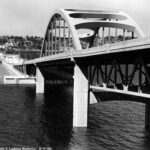
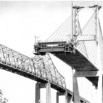
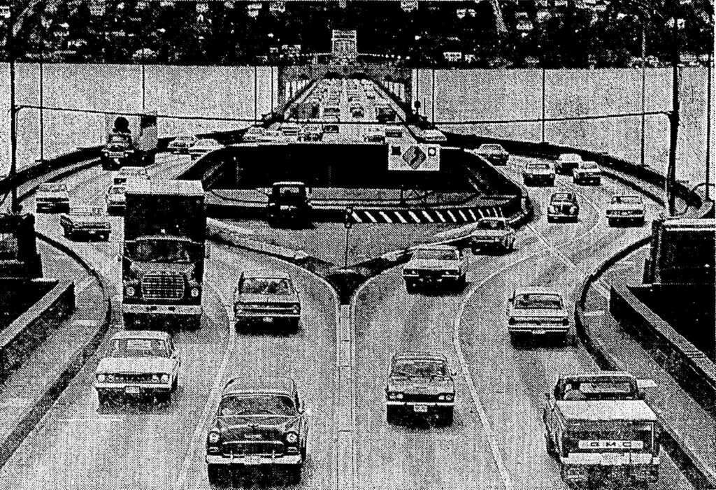
The draw span was another interesting feature of the bridge. Affectionately known as “the bulge,” it was a novel solution to the marine navigation problems of the 1930’s. The navigation spans at each end of the bridge had a minimum vertical clearance at high water of about 29 feet. For the 1930’s, this was hopelessly insufficient. Tall ships were still fairly common and another means for accessing the south end of the lake was needed.
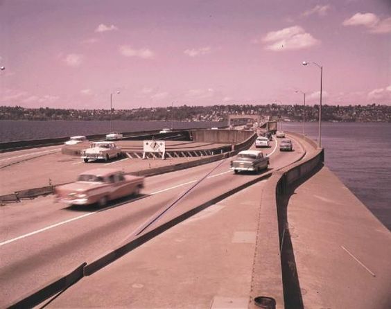
The solution was to provide a 200 foot opening in the bridge that could be retracted as needed to allow boats to pass. But to do this, there needed to be a place for the retracting portion of the bridge to slide back into and out of the way. Engineers solved this by creating a bulge in the bridge. During a bridge opening, the movable pontoon would slide back into a slot between two flanking pontoons. To create the slot, the roadway split onto the flanking pontoons. Using two 75 horsepower drive motors, the draw span could be opened in 90 seconds.
This “bulge” style draw span would be the de rigeur draw span design for floating bridges for the next 20 years. However, it had a number of short comings.
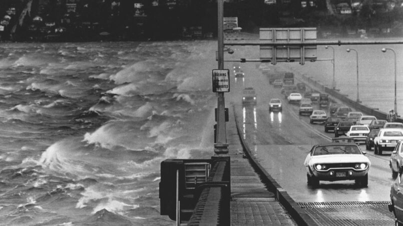
For those of you reading this blog who are not familiar with the climate in Seattle, with the exception of a few days in July and August, it generally rains constantly here. Any road here with a curve has likely seen at least one weather related accident. At the draw span, there are two chicanes that must be negotiated when crossing the bridge. And by negotiating these curves one needed to cross steel armored joints that were skewed with respect to traffic. Steel is very slick when wet and the skew angle made the situation worse.
It was not uncommon for inattentive drivers to miss the start of the chicane and wreck their cars at the draw span. There hundreds of such accidents. In one case, a teenage girl’s 1978 Plymouth missed the curve, left the roadway and landed in the lagoon at the center of the bulge. The car did not sink to the bottom of the lake because it became lodged in the underwater struts connecting the flanking pontoons. No one witnessed the accident and the car, hidden from view, went unnoticed. The girl was listed as missing. It was not until 1981, when construction workers were working to remove the draw span, that the car discovered with the girl still inside and a nearly two year mystery was finally solved.
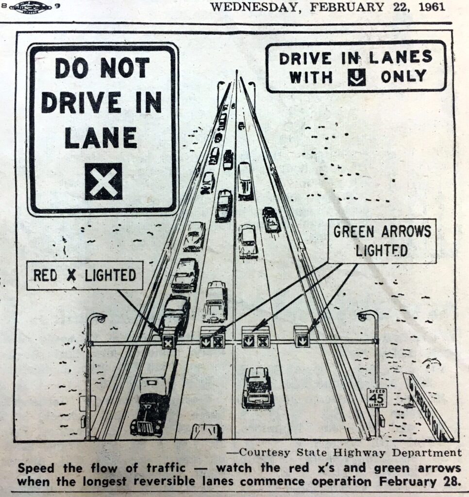
As traffic volumes grew, reversible lanes were added to the bridge so that the number of lanes going in one particular direction could be adjusted to meet peak flow. Lighted signs with green arrows and red X’s were used to denote which lanes were open. When one of the center lanes was reversed from its normal direction, this meant that vehicles could be headed in opposite directions yet share a single side of the bulge. Add to this the wet steel joints and inherent risks associated with the chicanes and the problem was compounded.
Movable bridge regulations require that a physical barrier be present when the bridge is operated. To achieve this on Lacey V. Murrow, steel nets were dropped from steel gantries at each end of the draw span. These steel nets became cumbersome to maintain and were eventually abandoned. Their use could disrupt an opening and their unreliability became irksome to the traveling public and to the bridge crew that had to fix them.
With the construction of the new East Channel bridge between Bellevue and Mercer Island in the late 1970’s (providing 70 feet of vertical clearance) the floating bridge draw span was now rendered obsolete. This, coupled with the safety issues with the bulge, inevitably led to its removal in September 1981. The draw span was replaced with straight, fixed pontoons. The reversible lanes would endure until replaced by the dedicated I-90 express lanes on the Third Lake Bridge.
Where the rest of the pontoons on the bridge were joined by bolted joints, these new fixed pontoons used to replace the bulge were joined by post-tensioning tendons. This fact will become important during the sinking in 1990 as these pontoons actually prevented more of the bridge from sinking.
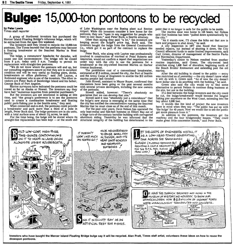
The bulge was sold to a local group of investors who had big plans for this hunk of floating bridge. However, they ran into an interesting problem. The width of the draw span was too wide to fit through the locks. Without some amount of disassembly, there was no way to get the draw span off the lake.
The draw span was towed to the south end of the lake, near Gene Coulon Park and moored until a solution could be found. But this would not be the last we would hear of the old draw span. One day curious onlookers watched as the old draw span took on water and slowly slipped below the surface. It didn’t have to go far – the water was shallow and even completely submerged, the luminaire poles could still be seen sticking out like a hand waving and saying “here I am!”
Alarmed, many calls were made to Bridge Maintenance. Hurry! Do something! A piece of your bridge has just sunk! When the bridge crew went down to investigate, they discovered it was just the old draw span, long ago sold and no longer owned by the State. Soon after this episode the luminaires were cut off the draw span and it was all but forgotten. While its true fate remains unknown, it is believed to still be on the bottom of the lake, in shallow water somewhere near Coulon Park.
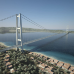
The Murrow Bridge was the first bridge of its kind – just like the first model year of a new car model, there were some things that worked well and other things that didn’t. Floating bridge engineers would learn from its design and improve upon it for subsequent designs. And some features are still in use on Washington’s newest floating bridge, the new Evergreen Point Floating Bridge which opened in 2016.

Still, the bridge was difficult to maintain and woefully inadequate for the 52,000 vehicles that were using it each day by 1975. When originally built, it was only expected to carry 2,800 cars a day! With sidewalks only 4 feet wide, the only people who would use such a path were the maintenance personnel. By the late 1970’s, engineers were coming to terms with the fact that the bridge needed renovation if it was to become part of the last link in the interstate highway system.
In the next installment of The Bridge Guy, we’ll take a trip back in time to November 25, 1990. We’ll take an in-depth look at the events that led up to the sinking of the Lacey V. Murrow Memorial Bridge during renovation, the immediate impact that the sinking had on the region and the litigious aftermath. What was planned during the renovation? What caused it to sink? What was the worst case scenario that kept Department of Transportation managers and engineers awake at night? Why did Governor Booth Gardner appoint a Blue Ribbon Panel to investigate the sinking and what did they recommend? Check back next week for more!
Views: 946