Use the right tool for the job – great advice when working on your car, your home or just about anything. The same goes for the use of retaining walls. You wouldn’t use the handle of a screwdriver as a hammer, just like you wouldn’t use a semi-gravity wall where a soldier pile would be more appropriate. In this edition, we’ll take a look at some applications for different wall types and how engineers go about designing them.
Semi-Gravity Walls
These walls are typically constructed from reinforced concrete and consist of a stem which is supported by a spread footing. Lateral loading applied to the wall tends to cause the wall to overturn about its toe. In resistance to the applied lateral loading is the weight of the stem, the footing and the retained mass sitting on the heel of the footing. By moving the stem towards the toe, the heel is enlarged and the amount of mass participating in resisting overturning is increased.
This type of wall must be stable both in a global sense and in a structural sense. For global stability, we’re interested in overturning stability, bearing stability and sliding stability. The designer will manipulate a number of variables in order to satisfy all of the stability checks – like footing width and stem location relative to centerline footing.
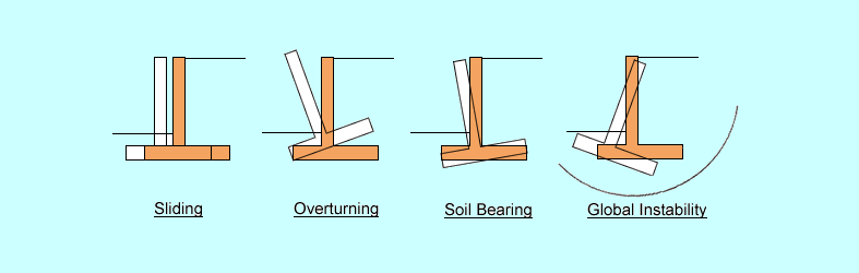
Overturning stability checks the susceptibility of a wall to tipping. This is done by determining the location of the resultant vector acting on the footing. To do this, you take the moments tending to cause the wall to tip over then subtract the moments tending to cause the wall to right itself and divide by the total vertical load on the system. This value, we will call it X, is the distance from the toe to the resultant vector. Most codes require that a stable wall have this resultant vector located within some distance of the center of the footing – usually the middle third or middle two-thirds. This ‘safe’ region is known as the kern of the footing.
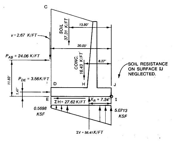
Bearing stability checks the applied load of the footing with respect to the soil it needs to bear on. Similar to the overturning check, we determine the effective bearing area of the footing. The effective bearing area is linked to the location of the resultant vector, so its location is essential to both calculations. Once we do that, we divide the total vertical load by this area to determine the effective bearing stress at the toe of the footing. If this bearing stress is less than the allowable values given to us by the Geotechnical engineer – all is well.
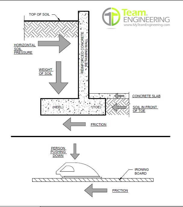
Sliding stability checks for the susceptibility of the wall to translation relative to the ground. This is a simple friction check. The total lateral load on the system is compared to the friction resistance. The normal force (total vertical load since the wall is plumb) is multiplied by the friction coefficient, usually given to us by the Geotechnical engineer using Rankine theory which gives us the sliding capacity. If capacity is greater than the demand, all is well.
Most wall designs today follow the Load and Resistance Factor Design (LRFD) methodology. In LRFD, maximum and minimum load factors are given depending on the calculation being performed. In a global stability check at the Strength or Extreme Event limit states, maximum load factors will be applied to forces causing overturning while minimum load factors will be applied to forces resisting overturning. In this way the most statistically accurate factor of safety is applied to the wall.
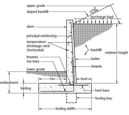
Once the global checks have been satisified, we can check the structural design of the wall. The footing toe is designed as a cantilever fixed at the face of the stem. The bearing pressure pointing upward causes tension in the bottom of the footing, which needs to be reinforced. The footing heel is designed the same way, with the retained mass sitting on the heel pushing downwards causing tension in the top that must be reinforced. The stem is designed as a cantilever fixed at the top of the footing. Loads forcing the stem outward cause tension in the far face and this is reinforced appropriately.
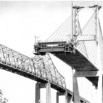
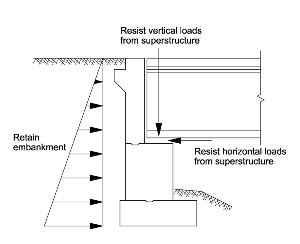
A typical application for a semi-gravity retaining wall is as a bridge abutment. An abutment is a special type of bridge pier that acts both as a support for the bridge superstructure but also helps retain the embankment leading up to the bridge structure. Abutments benefit from the additional dead and live load from the bridge superstructure in that it helps resist lateral loads.
A good rule of thumb for proportioning a semi-gravity footing width is to use 70% of the overall height of the wall in a high seismicity location and 60% for low seismicity areas. This helps ensure the resultant is within the allowable kern area and keeps bearing pressure demands within acceptable limits. With all things in design, these are just good rules of thumb and the design should be based on calculations and good judgment. Good soils or rock might mean less footing is required for a given wall height, whereas poorer soils may require larger footings to keep Service limit state pressures within acceptable limits in order to prevent excessive settlement.
A semi-gravity wall that is used as a bridge abutment has a number of advantages. The top of the wall – usually made from reinforced concrete – offers an advantageous perch for setting the girders for a bridge. The wall itself is usually sufficiently wide so as to preclude buckling in the transverse direction, not so with columns. And in seismic regions, since the abutment is already being used to resist lateral loads, the wall can often be designed to take additional seismic loads with little extra effort or materials.
As pure retaining walls, however, semi-gravity walls offer some drawbacks. They are usually only suitable for fill situations, usually requiring shoring and excavation to be built. Cost-wise, structural earth walls are generally cheaper while functioning in much the same way. Unlike structural earth walls, semi-gravity walls do not tolerate differential deflection well, often resulting in cracks.
Cantilevered Walls
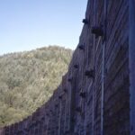
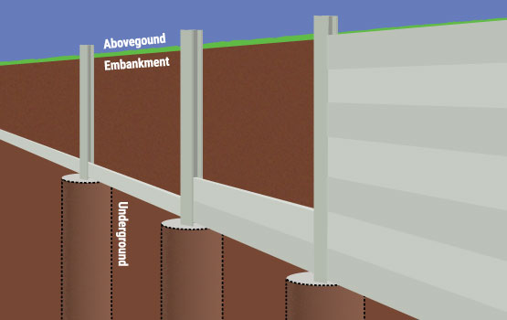
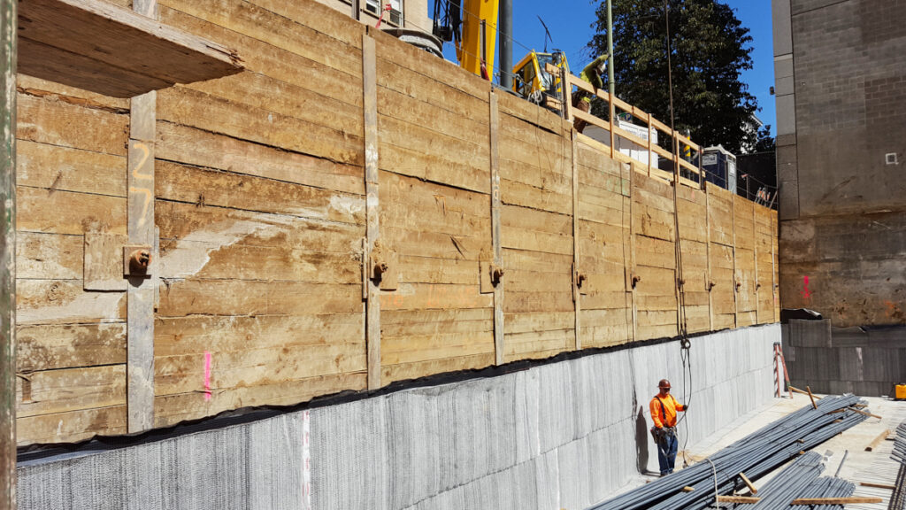
This type of wall uses distinct elements that are installed separately, then joined together to resist load. On common example is a soldier pile wall, so called because it looks like soldiers lined up in formation. Steel H or W sections are installed in bored holes – like a fence – and grouted in place using Controlled Density Fill (CDF) or lean concrete. Lagging – boards or plates that span between the soldier piles – are then installed to transfer the earth pressure to the soldier piles. Lagging is commonly made from lumber but steel or even concrete panels have been used.
The design of a cantilevered wall is based on global force balance in the system – essentially achieving equilibrium. This is done by installing the piles deeper into the ground to engage more passive pressure and counteract the applied loading. In doing this, the weight of the wall itself is insignificant and is usually neglected in wall design. This is one of the fundamental differences between a cantilevered wall and a semi-gravity wall.
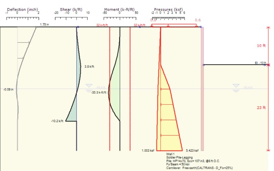
In a cantilevered wall system, retained soil exerts a distributed load on the wall elements which induces bending moment into each element. Where the element enters the soil, this bending moment is counteracted by the passive soil in front of the wall. This exerts an equal but opposite load on the element. At some point below ground the total load on the element will be zero. This is the point at which load balance is achieved in the element. The elements are sized based on the maximum bending moment, which usually occurs slightly below ground level.
The load applied to each discrete element is usually distributed by tributary area – the spacing of the elements. Soil loads are computed as pressures – force per unit area. If the area is known, then the force applied is known. Below ground level, applied load is based on the effective area of the element itself. Passive pressure is applied based on the concept of soil arching – this assumes that the structure is stiffer than the surrounding structure and that soil load arches into the elements, increasing the effective area for passive load.
Cantilevered walls and the balanced load approach generally work well on their own up to about 20 feet. Beyond this the section required to resist the moment is generally too large to be practical or top of wall deflection becomes excessive. In these cases, engineers often use tied back cantilevered walls.
A tieback, also known as a ground anchor, is a method of transferring most of the load from the wall elements to the earth behind the wall. They act like suspenders to keep the wall from falling over. Ground anchors themselves are grouted prestressing strand or bar that is bonded in place and then tensioned, much like post-tensioning tendons. Anchors are typically locked off at about 60% of their factored design load to help stabilize the wall elements.
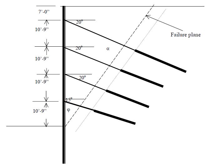
By using ground anchors, the wall elements act like continuous beams with the anchors acting as supports. Bending moment is better distributed than an unanchored wall, resulting in lower moments which results in smaller sections being used. The size of the section essentially becomes tied to the spacing of the anchors rather than to wall height – meaning greater economy with large walls.
Walls with ground anchors are designed with a different pressure distribution due to the presence of the anchors. Anchors are spaced to try and achieve the same amount of load in each anchor using tributary area. Since anchors help balance the applied load, the depth of embedment of the wall elements in a tied back wall is usually less. In a cantilevered wall, the ratio of embedded length to exposed height is 2 to 3, depending on the quality of soil. In a tied back wall, this same ratio can be 0.5 to 1.5.
Soldier pile walls are very common and are used extensively as shoring walls. Permanent soldier pile walls usually have a cast-in-place fascia applied to take the place of the timber lagging as it deteriorates. A fascia panel also beautifies a soldier pile wall, which for its simplicity of design could also be described as ugly.
Which tool is right for the job? In practice, the Geotechnical engineer will make the determination on the wall type most suited to a particular site. This determination is based on soil properties, the purpose or use of the wall and cost. The structural engineer may be consulted as to any special loading requirements, but any design cannot begin without earth pressure diagrams or parameters.
Another consideration to keep in mind during the design of a retaining wall is water. The life giving element of our natural world is in reality one of the most destructive forces on Earth. Earth pressures for design will generally assume well-draining, granular soils. To aid this, weep holes are generally provided to allow an exit for any water and sometimes under drains – perforated pipes – are provided at the base of the retained mass to prevent water build up and drain water away.
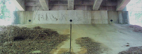
Standing water that is retained, like in a swimming pool, exerts hydrostatic pressure on a structure. This pressure can be immense if allowed to build up. Since most retaining wall designs assume no hydrostatic pressure, a plugged weep hole or underdrain or poor backfill material can allow excessive hydrostatic pressures to build up that may not have been designed for. This can lead to problems with global stability, though usually structural distress will not be readily apparent.
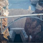
The right tool for the job – the right wall for the job. Retaining walls may be the sidekick of a bridge, but they are important in their own right. Cut and cover tunnels, which are essentially underground bridges, use retaining walls. Shoring walls are essential for the construction of bridges. And without a semi-gravity abutment, where in the world would we be?
Views: 1527