I was recently afforded the opportunity to tour the first prestressed concrete factory in the United States, right here in Washington State. The Concrete Technology Corporation (CTC) was founded by brothers Thomas and Arthur Anderson in 1951 on 30 acres located on Tacoma’s Blair Waterway. The plant’s opening came after a year of investigation into the viability of prestressed concrete as a business venture. After a tour of Europe – the home to nearly all of the prestressed concrete structures in existence at the time – the Anderson brothers became convinced their business would succeed.
And it didn’t just succeed, it has thrived! Through successful marketing and promoting of the prestressed concrete concept, CTC was able to grow rapidly. The main plant was operational by 1960 and a further expansion was added in 1967 as demand for prestressed products continued to grow. Further expansion in the 1970’s allowed for the addition of new products, including the construction of a graving dock.
Today, the plant has over 150,000 square feet of enclosed production facilities, including a state of the art batch plant for making concrete and shops for carpentry, reinforcement and welding fabrication. The plant has several mobile and gantry cranes for moving large products around and is capable of shipping products to customers via truck, rail and ship.
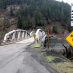
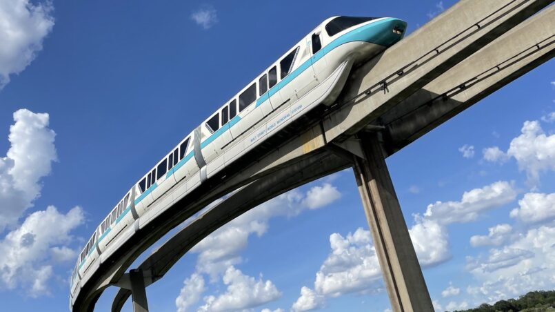
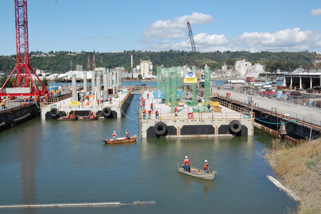
Among the notable projects built using CTC products are the girders used for the Seattle and Walt Disney World monorails, Cheney Stadium, Humboldt Bay Bridge, girders for the Mercer Island Lid and several successful attempts at breaking their own records for the longest prestressed concrete girders ever built. Pontoons for the Hood Canal Bridge and the Evergreen Point Floating Bridge were constructed in CTC’s graving dock.
And after nearly three quarters of a century, CTC is still on the forefront of prestressing technology. After my tour, I was able to witness a roll test of a prestressed concrete girder as part of research project championed by the University of Washington and the Washington State Department of Transportation (WSDOT).
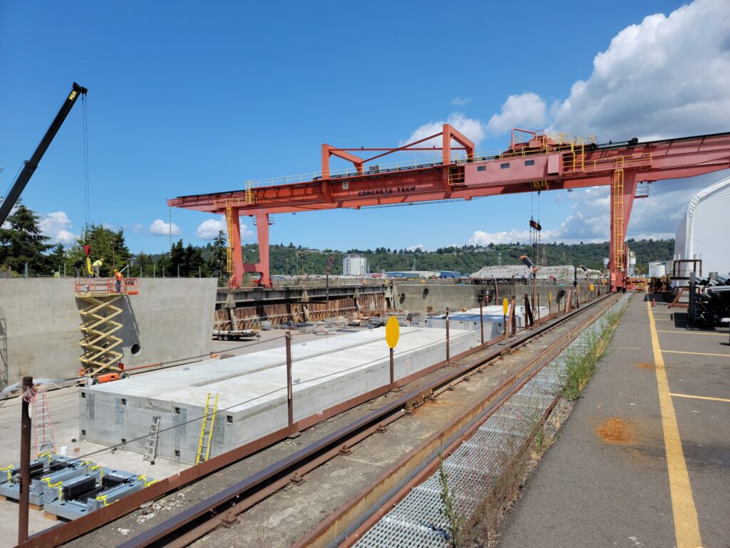
One of the first items of interest when visiting CTC is the large outdoor gantry crane. CTC uses the crane to proudly advertise their brand, but the crane isn’t just for looks. As I understand it, the crane came as surplus from a salvaged cargo ship. However, when it arrived it was too small for its intended use over the graving dock. So CTC enlarged the crane and even added post-tensioning strands (harped, of course) to help strengthen it. The last time I saw this crane it was white and now it is orange.
During my visit, the graving dock was being used for a well deserved maintenance project. A new gate for the dock was being built. Once complete, the dock will be flooded and the gate will be able to be floating into place by tug boat. The gate is then ballasted down into place, after which the dock can be dewatered for its next use. After years of use, the old gate as seen its day and will likely be recycled.
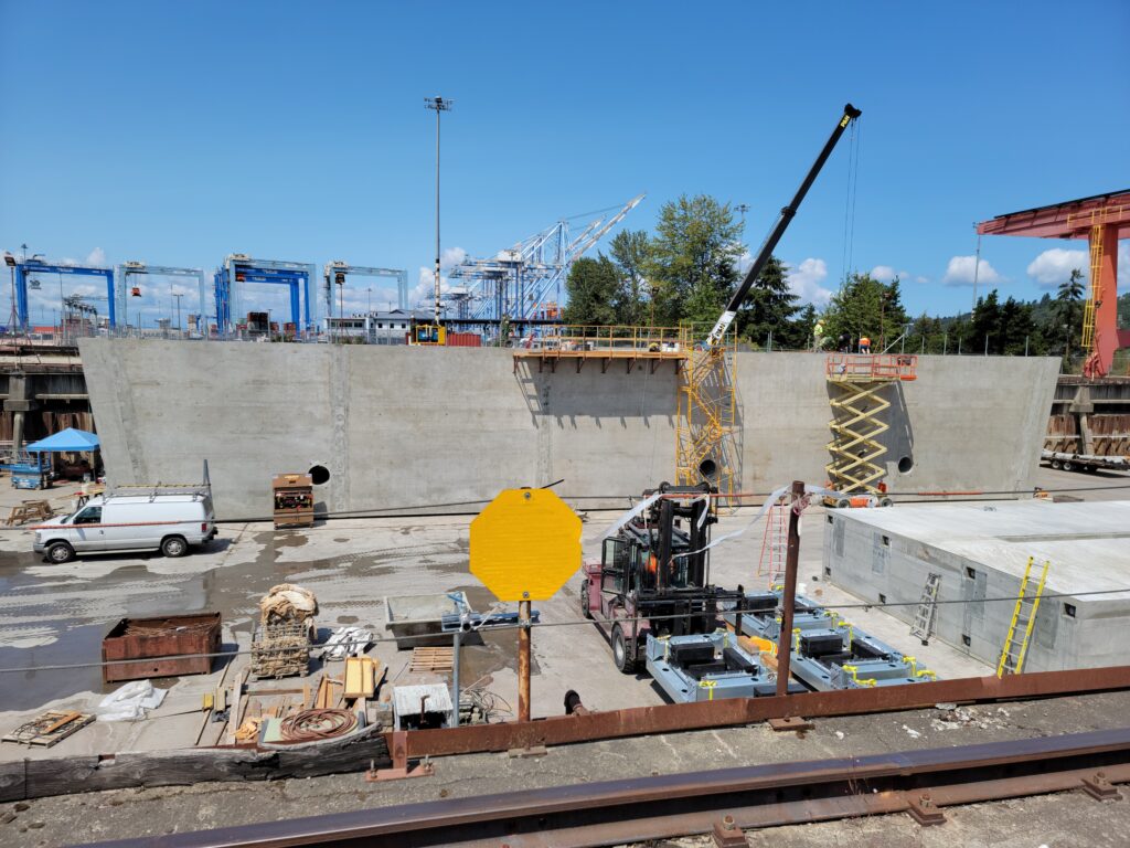
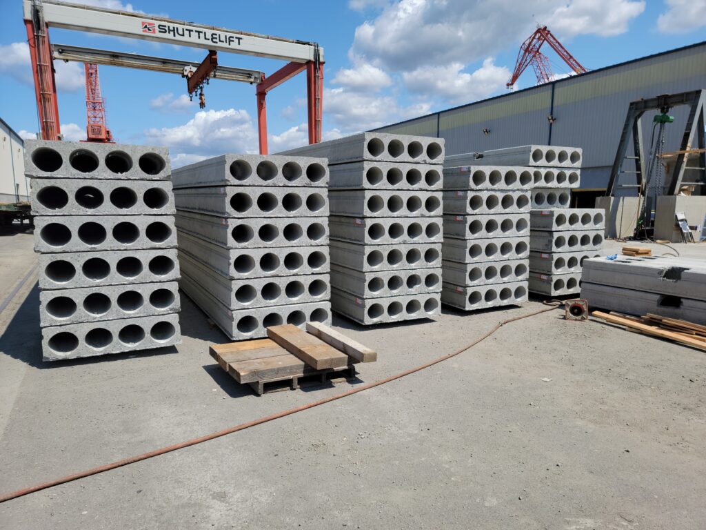
Among CTC’s many different prestressed products is prestressed piling. Piling is a widely used in the building industry in foundations. Another product is hollow core slabs. These hollow slab structures are used for detention vaults under parking lots and in building loading docks.
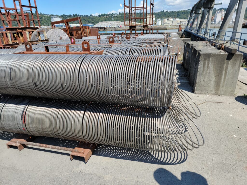
Hollow core is built using a zero slump concrete mix and a slip form casting system. The slabs have no mild reinforcement in them, only pretensioned strands. Once cured, the slabs can be sawcut to the customer’s desired length. Due to its high demand, hollow core remains one of CTC’s most popular and lucrative products.
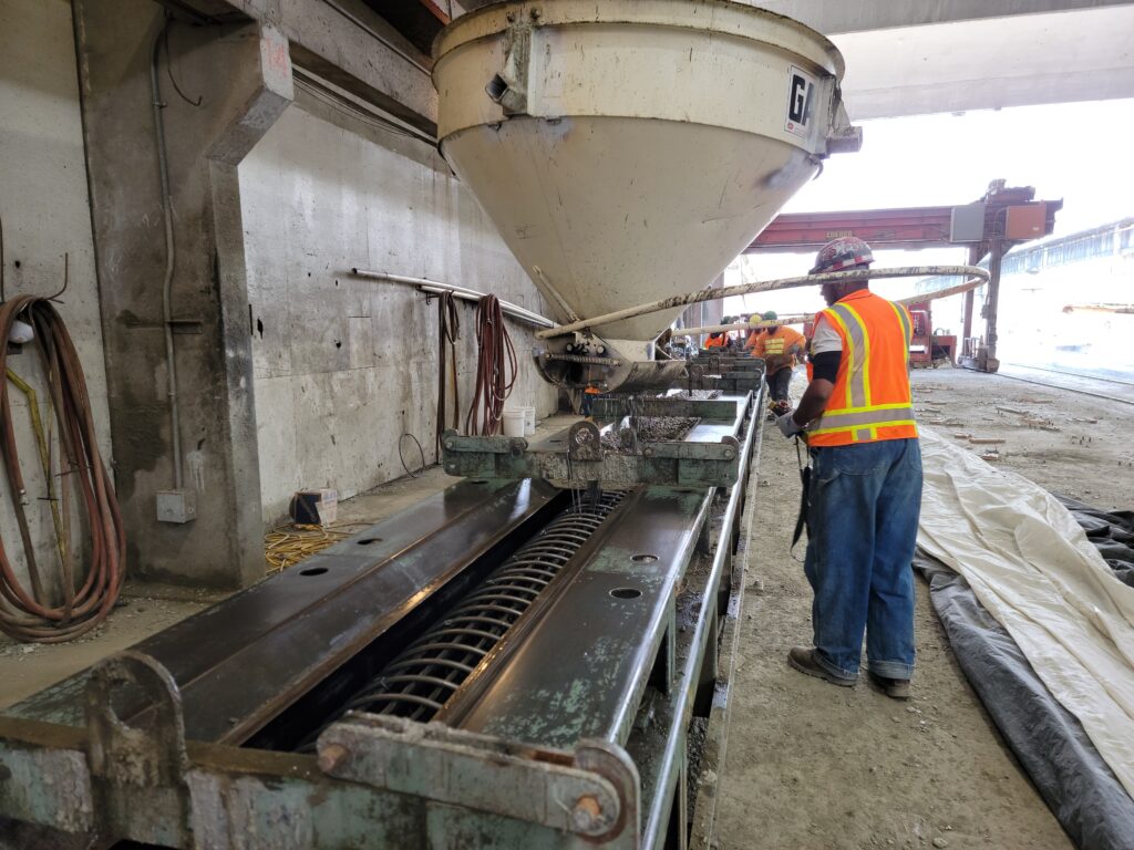
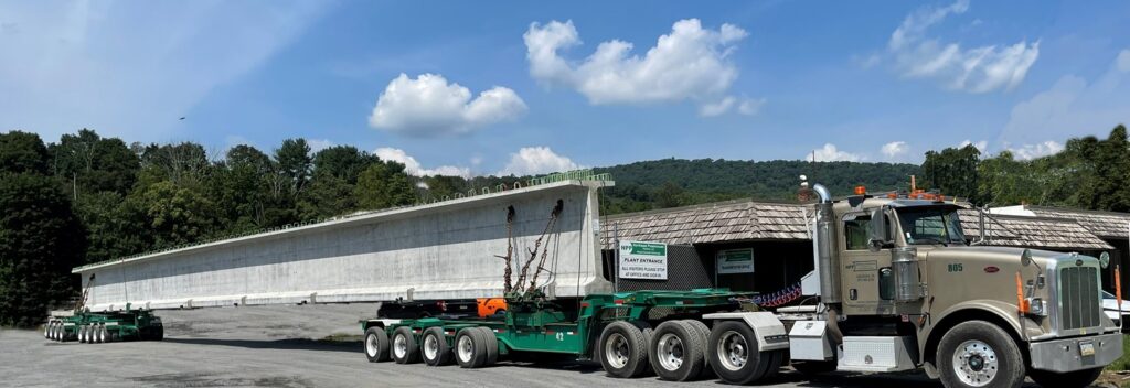
But what CTC is really known for is its girders. CTC has a long history of collaboration with WSDOT, having developed their first family of standard girders in the 1960’s and developing the new and improved wide flange girder family in the 1990’s. Even more recently, this collaboration has yielded the “super girder” shapes – the 95 inch and 100 inch tall girders, capable of an astonishing 220+ foot long, single piece girders.
With demand for girders increasing in the area – thanks to Sound Transit construction and WSDOT’s Fish Passage program – CTC recently invested in four new prestressing beds to keep up with demand. These new beds came on line around 2020 and allow the plant to produce as many as 8 girders at one time, depending on workforce availability.
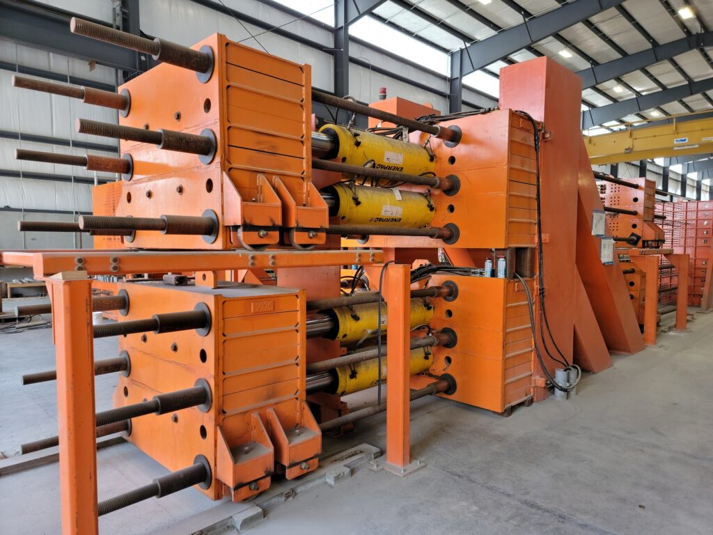
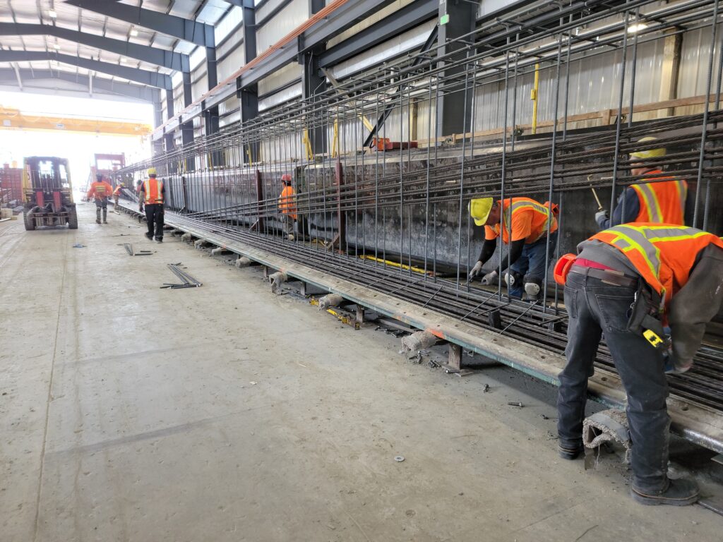
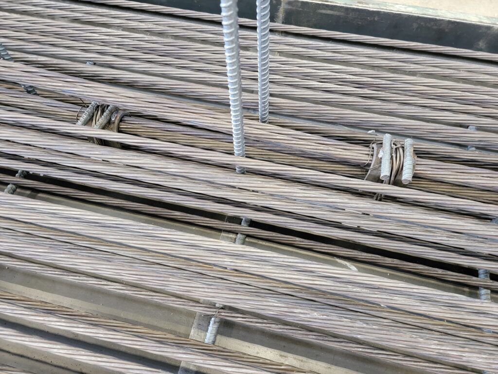
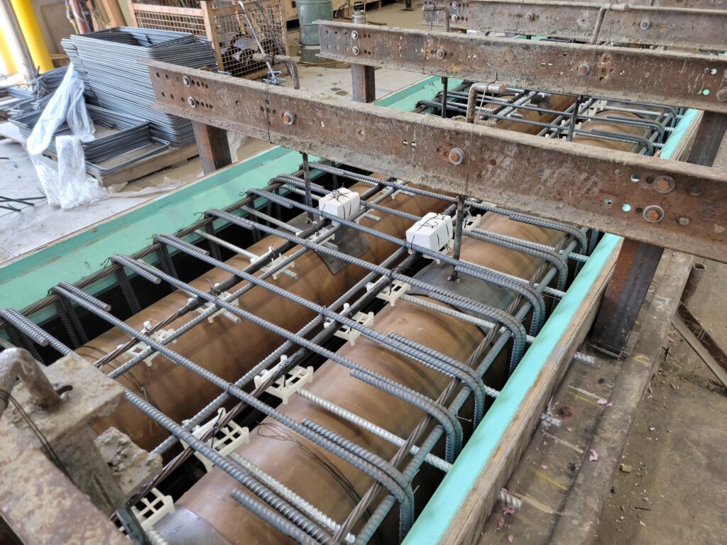
The plant is a 24/7 operation. Ideally, the plant can complete one girder per bed in 24 hours. First, new strand is placed and stressed. Next, iron workers place reinforcement per the approved shop drawings. Once completed, the forms are put in position and the concrete is placed. Sample cylinders are taken from the concrete mix so that they can be broken later to determine if the minimum concrete strength has been achieved. When the concrete curing is complete, the forms are removed for reuse, the strand is detensioned and the girder is lifted out of the bed and transporting to the storage area.
Concrete maturation is a complex process with several different variables, one of those being heat. Higher temperature increases the hydration reaction, leading to higher strengths in less time. CTC uses heated forms for its girders, achieveing temperatures as much as 175 degrees. The temperature of the forms is also tied to the temperature of the test cyclinders to ensure the curing conditions of both is as close to the same as possible.
In addition to the typical and easily recognizable WF style girders, CTC also produces prestressed voided slabs. These should not be confused with hollow core. Voided slabs have mild reinforcement in addition to prestressed strand and are used for shorter span bridges up to about 80 feet or so.
After our tour, I witnessed a full scale roll test to failure of a surplus Sound Transit girder. This test was just one of many such tests used to inform researchers on the lateral strength of girders during transportation.
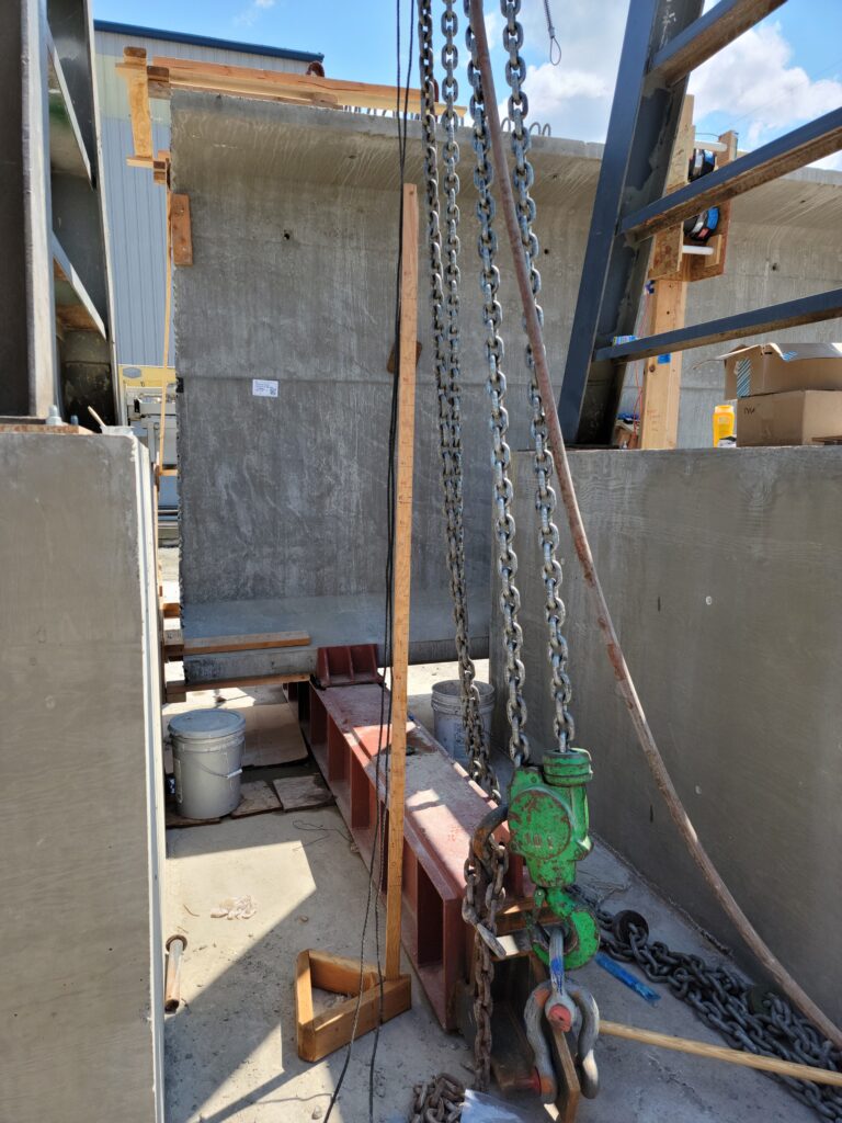
When girders are transported from CTC to the job site, most of the time they are shipped using specially rigged trucks. The bunking points – the support locations on the truck – are selected by the engineer so as to keep the temporary stresses in the girder within code allowables.
Sometimes trucks must negotiate roadway cross slopes that cause the truck to lean to one side, causing the girder to be loaded laterally. WF style girders are very strong in their primary axis of bending (bending caused by loading applied vertically) but have little resistance to twisting (torsion) and to lateral bending (bending caused by a horizontal force). When a truck leans or rolls, it puts unintended stress on the girder.
Hopefully this research will help AASHTO provide guidance to owners and design engineers on how to design for such stresses. But it comes at the cost of a few girders being intentionally roll tested.
CTC fabricated two roll brackets attached to each girder end. To this, a makeshift gauge showing the various lean angles and plumb bob are used to show the amount of roll the girder is at during the test. Two electric hoists are used at each end to cause the girder to roll. Strain gauges and other instrumentation are applied to the girder to monitor stresses at various points during the test.
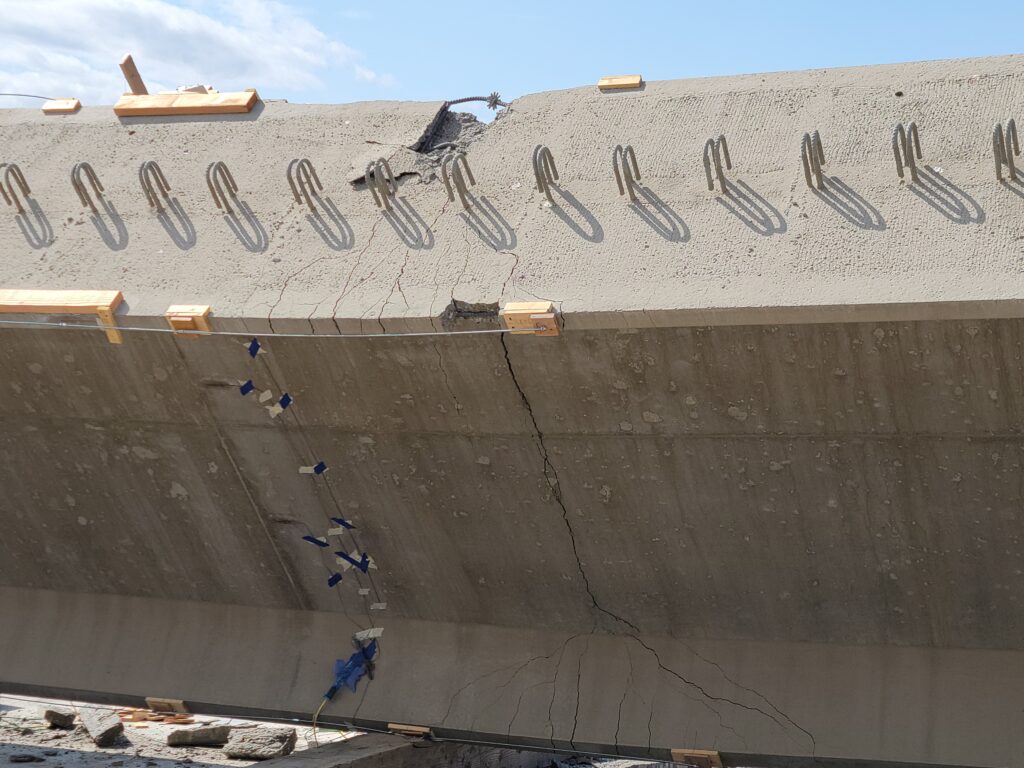
The girder was rolled at 5 degree increments up to about 30 degrees, and then progressed at 2-3 degrees each until failure. Dr. Stanton predicted failure at 33 degrees based on previous behavior, especially since the temporary top strands had been removed. But it ended up far better than that!
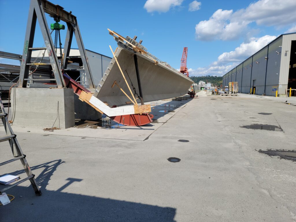
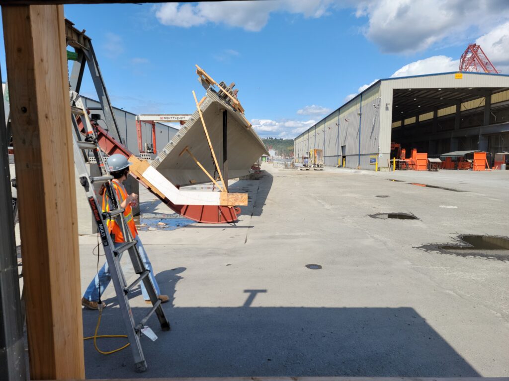
Ultimately, the girder failed at just over 40 degrees of roll but only after sitting for a bit. Cracking in the tip of the top flange had been occurring – indicating classic ductile failure. But once it reached such an extreme angle, the flange concrete eventually reached its crush strain – 0.003 – crushing the concrete, at which point the beam lost all residual strength and dramatically failed.
That’s all for this edition of TheBridgeGuy. For more on prestressed concrete, check out ‘Everything you wanted to know about prestressed concrete – but were afraid to ask.’ A special thanks to Austin Maue, Concrete Technology’s Chief Engineer, for the tour of the plant. It was my first visit to the plant in a while. I was last out there c. 2007 to see the Hood Canal pontoons under construction. Bridge engineers really do rely on the talented professionals at plants like CTC to make their designs become a reality – without them our designs would just be lines on a page.