
After only two months with my new employer and I’ve already received some of the best training of my career. The week long workshop on load rating was a good refresher for me but was also a great introduction to how the Corps handles this sometimes tedious but important bridge engineering task. In this edition of TheBridgeGuy, we’ll discover what load rating is, why we do them and why it should matter to you.
During the design of a bridge, the engineer is, through iteration, comparing the load demand of individual components against their capacities. In every case, the available capacity of a component must be greater than the demand placed on it. As design progresses, the engineer can add or remove reinforcement, increase or decrease the size of a component or otherwise change the design to satisfy this basic constraint.
However, once a bridge is constructed, it is very difficult or impossible to change a component’s capacity to carry load. What is more likely is a component’s tendency to lose strength as a result of environmental factors, reducing its ability to carry load over time. The ratio of a component’s capacity to the demand on it is known as a capacity to demand ratio (c/d). When this ratio is greater than 1.0, all is well. But when it falls below 1.0, a component is said to be overstressed. Overstressing bridge components can lead to failure and possible collapse.

Historically, the legal loads allowed on our public highways have gone up over time, not down. Trucks are heavier now than ever before. This is particularly important for older bridges that were designed to older load standards. So you end up with an older bridge that was designed for a lower load standard, constructed of aging load carrying components that may or may not be as strong as they once were, which ends up carrying more load than it was designed for.
Provisions for evaluating existing bridges were first published in 1941 by the American Association of State Highway and Transportation Officials (AASHTO) in The Standard Specifications for Highway Bridges. This would become the first US bridge design code, and is notable for introducing the concept of load rating to the bridge engineering world for the first time. Incidentally, the Standard Specification would remain the main bridge design code in the United States for over sixty years, until finally being replaced by the current LRFD code in 2007.
But the Standard Specification rating system was imperfect, sometimes leading to widely varying results for the same bridge. AASHTO attempted to provide a unified approach to load rating with the Manual for Maintenance Inspection of Bridges (MMIB) in 1970. This manual coincided with the introduction of the National Bridge Inspection Standards, of which load rating played a significant part. After all, the entire purpose of inspecting bridges is to determine if they can safely carry load.
By the 1980’s, the shortcoming of the MMIB was becoming clear. In 1989, AASHTO released the first version of the Load and Resistance Factor Rating (LRFR) method, the load rating method used in the United States today. In 1994, the Manual for Condition Evaluation of Bridges (MBE) replaced the MMIB. Federal Highways (FHWA) further enforced the adoption of LRFR by the States in 1995.
So what is a load rating? At its simplest, a load rating is a number that indicates whether a bridge component can safely carry a particular live load. It is essentially a c/d ratio for live load. When performing a load rating, the engineer will compute the dead load demand, live load demand and capacity for every component on the bridge. The component with the lowest rating factor then governs the entire bridge. This factor then informs the owner about the practical limit on trucks using a particular bridge, including any restrictions necessary.
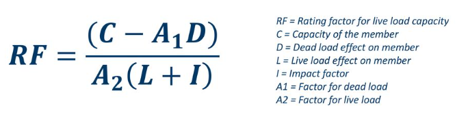
What the basic formula tells us is that when you remove dead load demand from the capacity, any remaining capacity left in the structure is available to carry live load. So the numerator is the capacity available to carry live load, while the denominator is the actual live load demand. If the ratio is greater than 1.0, then there is more capacity for live load than there is live load demand. If the ratio is less than 1.0, then there is more live load demand on the structure than the structure can be expected to carry.
The NBIS require an up to date load rating for all bridges over 20 feet in length that carry roadways that are open to the public. As a baseline, a load rating will be based on as built drawings for the bridge. Updated load ratings are required when the amount of load being carried by a bridge changes substantially (such as a deck overlay) or the condition of a component deteriorates substantially (such as section loss in steel gusset plates).
To better understand the three components of a load rating, we’ll over each separately.
Capacity
Capacity calculations are nearly identical to those used during design. This is why most bridges are load rated immediately after design is complete – it just makes sense. The MBE, the document which governs load rating, defers to the latest LRFD Bridge Design Specification for capacity calculations.
In addition to the typical LRFD resistance factors used for design, load rating also applies some additional reduction factors to account for redundancy and condition of a component. A lack of redundancy increases the risk that a deteriorated component could pose to the structure, which makes it an important consideration in the safe carrying capacity of a bridge.
Engineers rating an existing bridge will consult the latest inspection report for guidance on component deterioration. The MBE provides reduction factors that are tied to the NBI coding for the superstructure, but engineers can also reduce capacity as needed based on judgment and the actual condition of the bridge.
Dead Load
Dead loads are gravity loads for components on the bridge that do not move. This can be the self weight of the bridge load carrying members themselves or superimposed loads that the bridge carries, such as utilities.
Such loads are usually known with a fair degree of certainty. However, concrete and steel dimensions can vary somewhat. Unit weights for materials are also subject to variation. For this reason, a load factor is applied to dead loads during both design and load rating. Typically, dead loads other than utilities and wearing surfaces receive a factor of 1.25 under LRFR.
When additional dead load is added to a bridge, the load rating is usually updated to account for this. The increase in dead load reduces the amount of capacity left for live load, which makes an accurate accounting of all dead load important.
Live Load
There are three types of live loads that are considered in a typical load rating. Design loads, legal loads and permit loads.
Design load under LRFR is the HL-93 live loading used for new bridge design under LRFD. Since many older bridges were not designed for HL-93, it is not unusual to see these older bridges have design rating factors less than 1.0. This does not mean the bridge is unsafe. HL-93 is entirely fictitious and is intended to be an envelope truck representing the largest truck the bridge will see over 75 years.
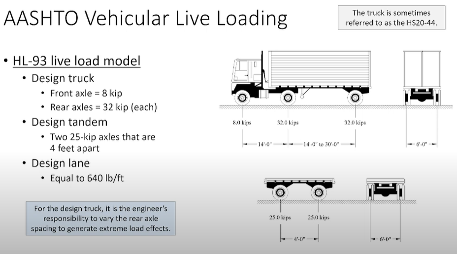
There are two design ratings, each with a different load factor on the live load. Inventory, which uses a load factor of 1.75 (equivalent to the Strength I limit state load factor used for design), and Operating, which uses a load factor of 1.35.
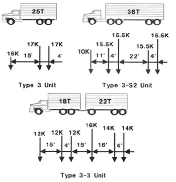
Legal loads are more realistic trucks that are intended to represent an actual truck you might see on the highway. These are considered the largest axles legally allowed to cross a public road without a permit. You may see weigh stations on highways – their function is to enforce these legal axle restrictions.
AASHTO specifies a number of different trucks that the States must consider, although some freedom is given to the actual states in this regard. The Type 3, Type 3S2 and Type 3-3 trucks are the basic trucks for consideration. Other legal loads include the notional truck, the legal lane load and single unit axles.
Since emergency vehicles often disregard load posting signs during emergency situations, FHWA has since required States to rate all public bridges for emergency vehicles. These loads can also be considered legal loads.
Legal loads get a load factor that is less than the design loads, usually 1.3.
Permit loads are trucks that may routinely use public roads but feature axles that exceed legal limits. They can also be unique vehicles or loads that use a bridge, such as tracked vehicles, military vehicles or equipment loads. Permit trucks usually fill one lane on a bridge with the remaining lanes being filled with legal loads. Permit loads also receive a lower load factor than design loads.
Live load application and distribution is a complex and tedious task. Trucks are applied to lanes, which are placed in accordance with the LRFD code. The number of lanes is the integer value of the roadway width divided by 12, although the MBE allows the actual number of striped lanes to be used in lieu of the LRFD lane number. Wheel loads within a lane are located no closer than 2 feet to a lane edge.
Only one truck is loaded per lane per span. To account for the possibility of multiple trucks being at a location at one time, the code allows for multiple presence of live load. A single lane is 1.2, two lane sin 1.0, three lanes is 0.85 and four or more lanes is 0.65.
A dynamic allowance is applied to axle loads. This accounts for the short duration increase in dynamic acceleration of a bouncing axle on a bridge. This factor increases axle loads by 33%.
Most analyses consider a single lane loaded across a bridge, which is then distributed to the girders for rating. The LRFD code has tables of distribution factors that can be used in lieu of more sophisticated analysis methods, such as a grillage analysis. When these factors are used, multiple presence does not apply. These factors are typically less than 1.0 and are multiplied by the per lane value of live load to get a per girder live load.
Unique to bridge engineering, we typically consider actual vehicle loads which consist of a series of point loads applied to a beam. An engineer will use the concept of superposition to consider the bending moments and shears on a beam under consideration. Superposition allows the effect of multiple load effects to be computed separately, then added to together to achieve the total effect.
To find the maximum bending moment for a moving load, the moving load should be located such that the center of gravity of the moving load is at the same distance from one support as the center axle is from the other support. In other words, the space between the center of gravity of the truck and the nearest axle should straddle midspan. The location of maximum bending is then located under the center axle. Note this is not usually at midspan as one would expect.
It is important to note that only the superstructure of a bridge is load rated. That is, everything above the bearings. Bridge decks are not typically load rated as they are assumed to be designed conservatively. Secondary members, such as diaphragms are also not typically rated. Therefore, it is usually the main longitudinal members that get rated for most bridges.
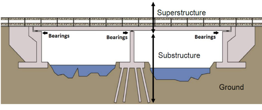
Although the substructure is not required to be rated, some States rate the pier caps (or crossbeams) for intermediate piers. Most substructure component designs are governed by lateral loads and not live load, although in pier caps this may or may not be so.
So if a rating factor greater than 1.0 is good and less than 1.0 is bad, what happens if a rating factor is less than 1.0? The owner will place weight restrictions on the bridge if this happens. But, there are a number of different outcomes from a load rating that need to be considered when restricting a bridge.
If a permit rating is less than 1.0, the owner may restrict the bridge to legal loads only. This typically doesn’t require a posted sign. Since a permit load requires a permit to operate on the requested route, the owner will inform the trucking company that the route with the restricted bridge is not available and the permit denied.
If a legal rating is less than 1.0, the owner will typically restrict the bridge to something less than legal loads. This is done by posting a sign and code reporting per the NBIS. The sign posted will usually give one or more trucks and their restricted weights. This data is usually available to truckers ahead of time in today’s day and age. However, it is important to note that many bridge owners are not in the enforcement business. Enforcement falls to law enforcement, and overweight vehicles are nearly impossible to spot.

The rating factors used to compute the posted tonnages are usually reduced by 0.3. If a bridge has a controlling legal rating of 0.3 or less, the MBE recommends closure rather than posting.
So why does load rating matter? For most of us, a restricted bridge may not matter at all. Load rating and load limits apply to the heavy vehicles on the road, not your Toyota. So there is little to be concerned about as far as safety for your typical commuter. But, for those of you that live on an island that is serviced by a load posted bridge, it may matter a lot. Heavy vehicles used to deliver goods and services may not be able (or willing) to cross the bridge. And then what do you do?
Views: 811