What do Robin, Kato, Sancho Panza and retaining walls have in common? They are all sidekicks, of course. And where would Batman, The Green Hornet, Don Quixote and – bridges – be without their sidekick? Well, we’re about to find out.

Retaining walls, or simply walls, are one of a myriad of transportation related structures that help the bridge to do its job. If the bridge is the main event or the main project, then the walls on a project are the supporting cast. In this edition of TheBridgeGuy, we’ll take a look at the supporting role walls play on bridge projects.
The basic definition of a wall is a structure or surface which defines an area. Historically, this was an apt definition. Our ancestors made widespread use of walls to keep out the unwanted, to keep in those who would try to escape or to provide a defensive barrier. In the transportation sense, we use walls to keep out unwanted material or to support loads, and sometimes both.

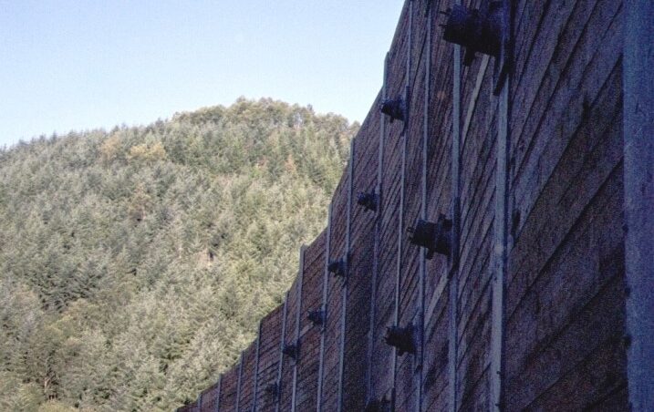
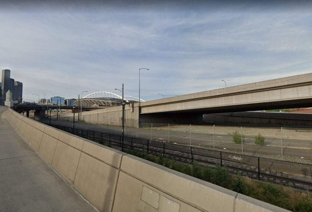
Starting with the National Environmental Policy Act of 1970 and the Noise Pollution and Abatement Act of 1972, roadway and other forms of noise pollution became regulated in the United States. While the way these Federal laws are enacted is beyond the scope of this article and are not fully understood by the author, suffice it to say that noise barrier structures are one way that noise along roadways can be abated. You may have seen these structures along a highway or interstate near you.
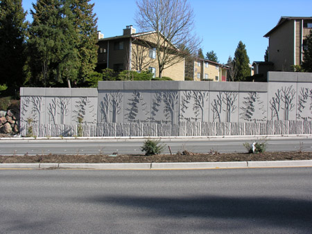
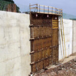
Noise barrier walls may be made of a variety of materials. Most modern versions are made from reinforced concrete. They often utilize architectural form liners and may include maintenance doors periodically. Many Departments of Transportation have their own standard designs. There are a variety of different types, either precast or cast-in-place concrete for the panels themselves. Substructures may be either spread footings or shafts. A common wall type in the northwest is a precast panel strengthened with pilasters. The pilasters are then bolted to pre-installed cast-in-place shafts. Through the use of cantilevering the panels, angle points can be made in the wall to satisfy any layout.
These walls keep unwanted material out – noise – while also supporting wind loads. Sometimes if placed near live traffic, these walls will incorporate a traffic barrier shape at their base and will be designed for traffic impact. While a barrier infinitely tall would be needed to keep out all sound, noise barriers such as these have been shown to be effective ay reducing noise levels by 5 to 10 decibels (dB), or cutting loudness of traffic in half. As an example, a 10 dB reduction of a tractor trailer passing by would reduce its sound level to that of an automobile.
Any transportation related walls that remain after excluding noise barrier walls would generally be considered a retaining wall, meaning they retain or keep out some material from a delineated area. Retaining wall structures can be broken down into three main types – gravity walls, cantilever walls and structural earth walls.
But before we delve into the different wall types – a word on lateral loading. Numerous individuals have contributed to engineer’s understanding of soil mechanics and the loads they impose on a retaining wall. Charles-Augustin de Coulomb studied lateral earth pressures as late as 1776 in addition to discovering Coulomb’s Law, which defines the force between charged particles in physics. William Rankine predicted active and passive lateral earth pressures, developing Rankine theory in 1857. Both methods for determining lateral earth pressures are used today.
In general, there are three types of pressures we need concern ourselves with – at-rest pressure, active earth pressure and passive pressure. Soil can be treated as a fluid and in many ways the principles of fluid mechanics apply when trying to determine lateral pressures. Water, when retained by a dam, exerts hydrostatic pressure – simply a function of the unit weight of water and its depth. As you go deeper in a column of water, the more pressure is exerted. Both Rankine and Coulomb sought to develop coefficients that could be applied to this hydrostatic pressure to account for the fact that soil is not wholly fluid and has some structure of its own.
At-rest pressure develops behind a retaining structure when the wall is inflexible and does not deflect under load. This magnitude of pressure generally develops at intersections of flexible walls with more rigid structures and behind gravity walls. At-rest coefficient will generally be less than 1.0.
Active earth pressure develops behind retaining structures that are flexible enough to deflect under load. Generally, cantilevered walls and semi-gravity walls are assumed to deflect. The magnitude of active pressure is about 10% less than at rest pressure. The active coefficient will generally be less than 1.0.
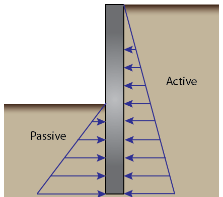
Passive pressure is a pseudo-pressure that can develop in front of a retaining structure and resists overturning. It is called a pseudo pressure because it only resists that which is applied to it, although the pressures predicted by Rankine and Coulomb can be quite a bit higher. Passive coefficients are generally greater than 1.0.
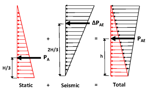
The above categories assume static behavior of the soil. But what about dynamic behavior during, say, an earthquake? In that case, an added increment is added to the pressure behind the wall. Two Japanese engineers – S. Okabe and N. Mononobe – developed the theory in 1926-29 that carries their names to this day. They expanded on Coulomb’s work to develop the dynamic increment that takes into account the movement of the soil mass during a seismic event.
There are other lateral loads related to the principles listed above. Live load surcharge is another lateral load applied to walls near bridges. Live load compresses the soil behind a retaining wall, which exerts a load on the wall. In many cases, typical highway loadings are approximated with a 2 foot surcharge – that is a two feet column of soil on top of the embankment which develops either active or at rest pressures as necessary.
So back to the different wall types…
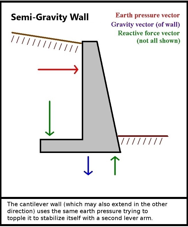
Gravity walls are exactly what you would think they are. Large, heavy structures that rely on their weight or the force of gravity to counteract the external loads applied. A further sub-type is semi-gravity walls.
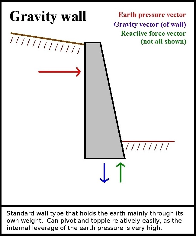
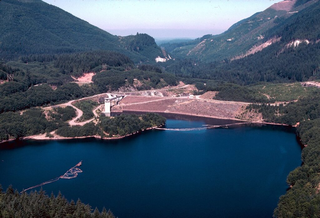
In the days of old when material was cheap and plentiful, gravity walls offered a simple way to retain large lateral loads. An analysis of a gravity wall is also fairly straightforward and nice factors of safety could be applied. Gravity walls can be made from any available material. Concrete blocks, mass concrete and soil have all been used to make gravity walls. The Howard Hanson Dam near Auburn, WA is an example of an earthen embankment structure than happens to hold back water.
Semi-gravity walls work in much the same way as gravity walls, only instead of using their own bulk to resist loading they also utilize the retained mass for resistance to external load and some cantilever principles. A common form of a semi-gravity wall in the reinforced concrete cantilevered wall.
True cantilever walls work by the fact that they are embedded or ‘fixed’ into the ground. They resist load primarily through flexure but do require a certain amount of balance between the applied earth loads and the passive load sin front of the wall.
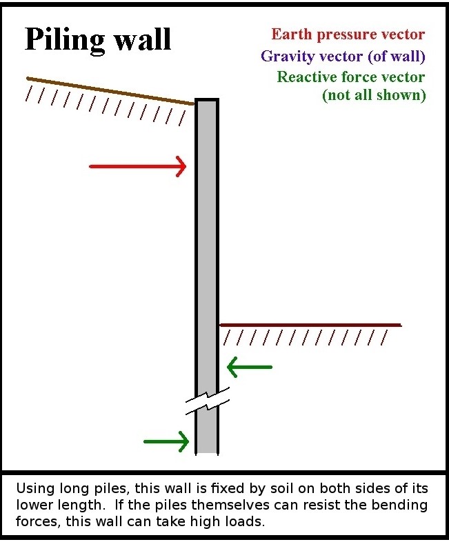
Soldier pile walls are a common example of a cantilever type wall. Also common are shaft walls – cylinder pile, secant pile and tangent pile all being sub-types of a shaft wall. A further complication is that cantilevered walls can be aided by ground anchors, also known as tiebacks or dead men.
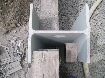
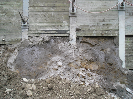
Soldier piles are essentially steel shapes, usually W sections or H sections which are either driven into the ground or set in drilled holes at discrete spacing. Lagging – timber being more common than steel or concrete – is used between the piles to transfer load using tributary area. The steel section is worked in flexure (bending) to resist the applied loads. In permanent applications, a concrete fascia is applied to the wall to replace the lagging after installation. Soldier piles may be used in either a cut or fill situation, however they lend themselves well to cut situations.
Cylinder pile walls are used like soldier piles, only a reinforced concrete shaft replaces the W-section. Shafts may be reinforced with a cage or with a W-section and assuming composite behavior. Cylinder piles are used only in fill situations since the shaft does not have any natural place to hold lagging. A fascia is applied to the shafts and the wall is then backfilled.
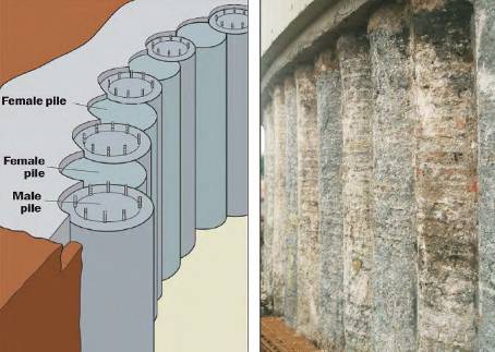
Secant pile walls are cylinder piles, only the shafts overlap one another to negate the need for a fascia or lagging. Lean concrete shafts are installed first at some discrete spacing. Structural shafts are then installed between and overlapping with the lean concrete shafts. This wall type can be used in cut scenarios.
Tangent pile walls are installed such that the structural shafts just touch each other, thus negating the need for lean shafts or lagging. Due to construction tolerances with shaft installation, these are less common.
Soldier piles work well without tiebacks up to about 15 feet. Beyond this, tiebacks may be needed to control deflections. However, taller walls have been used without tiebacks. Where tiebacks are not practical but height precludes the use of a traditional soldier pile, shaft walls work well. Their inherent stiffness means taller walls can be used before deflection becomes a concern.
And the final wall type is a structural earth (SE) wall. These are distinct from typical gravity earthen embankments in that they utilize internal means of resisting loads. Outwardly, they act much like a gravity or semi-gravity wall.
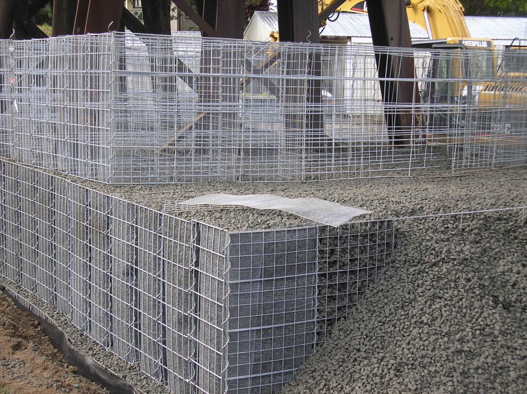
One sub-set of the SE wall family, Mechanically Stabilized Earth (MSE) walls are typically designed by Geotechnical engineers since the internal structural systems rely almost entirely on soil mechanics. A number of proprietary MSE wall types are on the market including Hilfiker and Tensar, among many others. Many types of fascia can be used with these types of walls, including blocks, precast panels, cast-in-place panels and shotcrete.
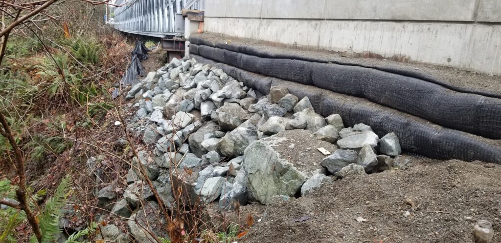
The other sub-set is Geosynthetic walls. These function much like MSE walls, only geotextile fabric is used to reinforce the earth mass. Also known as ‘pillow’ walls because of their lumpy appearance, shotcrete is typically the fascia of choice for these walls.
In general, the Geotechnical engineer will usually dictate the appropriate wall type based on the soil conditions in consultation with the structural engineer. Retaining walls reinforce the old adage – the right tool for the right job! It is important to select the correct wall type for a project, not only for the final loads but also by the method of installation. For example, if you need to shore a large cut area so you can put in a cast-in-place retaining wall and then backfill it, perhaps the shoring wall could be designed as the permanent wall?
So what do walls have to do with bridges? Well, without wingwalls a bridge would have no approach. Without shoring walls, your bridge abutment is never getting built at the proper elevation. Walls can help shorten a bridge, reducing the project cost while allowing the bridge to shine. Isn’t that the best purpose of having a sidekick?
In the next edition of TheBridgeGuy, we’ll discuss how engineers make these different wall types work in the real world. We’ll examine what goes into the design of a semi-gravity wall, some rules of thumb on their design and some of the advantages and disadvantages of this wall type. We’ll also examine cantilevered walls, using the same loads as a semi-gravity wall but with a completely different design philosophy. We’ll look at what makes a cantilevered wall type so versatile and useful in many different applications. Check back soon for more on walls – the bridge’s sidekick!
Views: 3447