In this edition of The Bridge Guy, we’ll examine the bascule bridge type – one of the three most common types of modern movable bridge. While the bascule type is broad, all of them have the common trait of rotating about a horizontal line laid transverse to the bridge centerline. This is where we get the fancy word bascule – borrowed from the French, meaning “rocking.” For example, a rocking horse in French is cheval a bascule. So ‘bascule bridge’ literally means ‘rocking bridge.’
The concept of a bridge that rocks dates back to the early drawbridge used in medieval times. These bridges were drawn by chain or rope and were usually not counterweighted. While drawbridges from this period were used for defensive or even military purposes, some small civilian bascule bridges were built to cross canals or streams. It was not until the advent of the locomotive in 1829 that bascule bridges came into their heyday. Harnessing the power of steam meant larger bridges – both wider and longer were now possible.
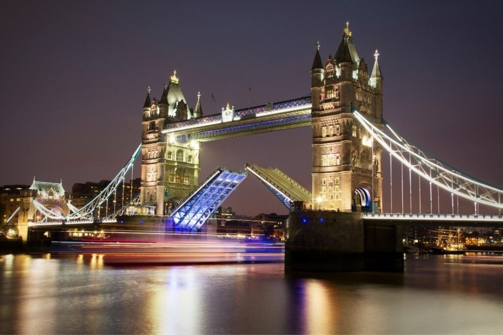
While there are many that could claim to the be the first, most consider the Van Buren Street bridge in Chicago (1893) and Tower Bridge in London (1894) to be the real forerunners for the modern bascule bridge. Sadly, of these two only Tower Bridge remains.
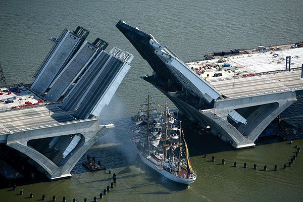
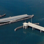
As previously discussed, the purpose of a moving span is to effectively increase the vertical clearance over the waterway on demand. When a bascule bridge begins to open, the vertical clearance begins increasing immediately. This means small boats can sneak under the bascule even with a partial opening. Compare this with the operation of a swing bridge where the span must be almost completely open for the same small boats to pass.
Bascule bridges, by virtue of their rocking movement, move up and away from the waterway. This means the waterway is not fouled by the bridge during an opening. This has a number of benefits – multiple parallel bridges may be placed next to each other with little to no interference, boats can come much closer to a bascule bridge before it opens and the waterway is virtually unrestricted during the opening.
There is also a safety improvement with certain kinds of bascule bridges. With the leaf up, the draw span itself acts as a barrier to accidental gate running. Bascules can also be adapted to any roadway width, unlike other types of movable bridges.
While the modern bascule type is based off of the medieval draw bridge, one major distinction between the two is the use of a counterweight. A counterweight is used to balance the moving part – known as a leaf – about the pivot point. The reason for counterweighting becomes clear when you think about the amount of power required to actually move such a large object.
When the power of steam came to be understood, it had all sorts of uses. One of the first innovations that steam brought about was the locomotive, but early automobiles were steam powered as were mills, factories and even electrical generators. With the perfection of the steam engine, engineers found uses for the new technology in movable bridges. At Tower Bridge, steam engines ran pumps which charged hydraulic accumulators. Pressurized water was used as a hydraulic fluid for opening the leaves.
Small draw bridges, such as the medieval draw bridge, could get away without counterweighting. Mechanical advantage and a strong back could be used to raise the bridge, while gravity could be used to lower it. But as the spans required increased and the loads required also increased, these bridges went from tiny specimens to absolute behemoths. And while steam had come to the rescue, to a certain extent, there were practical limits to the size and power of these prime movers.
Counterweighting the leaves of a bascule bridge was a simple and elegant solution to the problem of larger and heavier bridges. In principle, a heavy weight is applied to the heel end of a bascule leaf. Just like weights on a scale, the counterweight could be adjusted to counter-balance the weight of the leaf. In theory, the leaf could be balanced such that only a modest amount of power would be needed to offset the natural balance and create motion – Newton’s first law.
Most bascule bridges today are never perfectly balanced. Some net imbalance in the down position helps keep the bridge stable and reduces the tendency to bounce under live load. While this tends to necessitate the need for a larger prime mover, in the modern age where the energy supply is unlimited, this is of little consequence. The benefits on the structure of being stable offset the downsides of a larger prime mover.
Friction is perhaps the point of most concern in the bascule bridge. Friction in the bearings and machinery can be minimized through lubrication. Still, this merely reduces the friction coefficient. Since friction is a function of the weight of the structure, the bascule bridge becomes an extremely weight sensitive structure.
For example, take a 100 foot long leaf with a 20 foot heel. If you add 500 pounds of weight to the leaf 50 feet from the fulcrum, you’d need to add 1250 pounds of counterweight to balance the moments about the fulcrum. In total, you’ve just added 1750 pounds of weight to the fulcrum. That multiplied by the coefficient of friction gives you the extra friction force that the drive machinery must overcome to open the bridge. Friction is directly proportional to the weight added.
Many bascule bridges use open grid decks in an attempt to reduce the weight of the leaves. While novel in concept, open grid decks have a number of draw backs. Most importantly, they are extremely susceptible to fatigue cracking over time. They also provide no protection of the truss, floorsystem or centerlocks to dirt and debris from the elements, necessitating more maintenance.
The bascule bridge type can be further divided into three sub-types – trunnion bascules, rolling lift bascules and the Rall bascule.
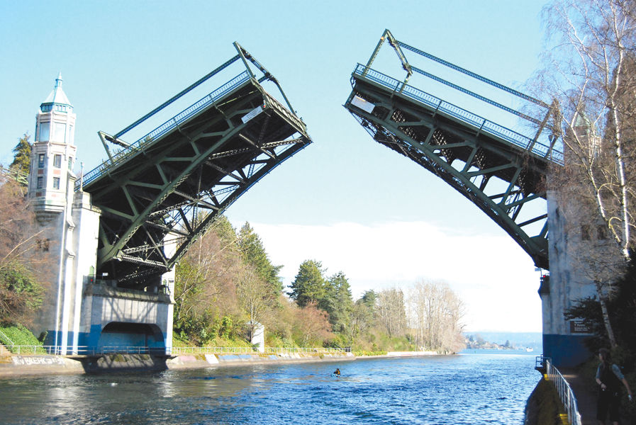
A trunnion is like an axle. In the context of a trunnion bascule bridge, they are the pivot points about which the leaves pivot. This sub-type can be further refined into bridges with the counterweight above the roadway deck and bridges with the counterweight hidden or below the roadway deck.
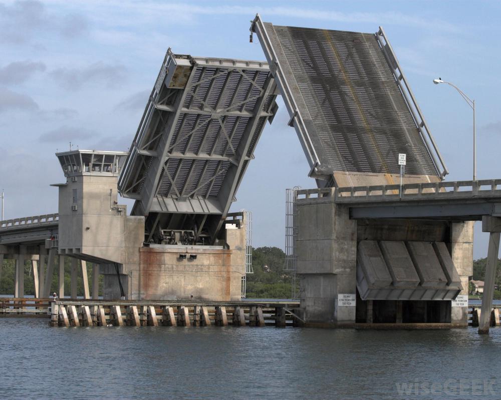
Trunnion bascules were a refinement by Joseph Strauss who opened his own company designing and building these types of bridges. Probably the most common type is the “Chicago” style bascule, named because of its widespread use in crossing the Chicago river. In a Chicago style bascule, large bascule piers contain the trunnion, counterweight and provide a pit for the counterweight to move in and out of during operation. In this way, the operating machinery is hidden from view. These bridges may be either double or single leaf designs and are characterized by a “break-in-the-floor” where the leaf rises when opening.
Another type of trunnion bascule, though less common and also popularized by Strauss is the heel trunnion. In this type of bridge, the counterweight hangs overhead. At the time, one of the major costs associated with Chicago type bascule bridges was the creation of a pit for the counterweight. To minimize the pit size, the moment arm of the counterweight from the trunnion was reduced which increased the needed size of the counterweight. Strauss solved this by placing the counterweight overhead. Another advantage was the relatively low profile of the deck – Chicago style bridges often need fixed approach spans in order to meet the high bascule piers. With the heel trunnion type, the need for long approach grades is minimized.
Due to its articulating nature, the heel trunnion type has two trunnions instead of one and several articulating pins that allow the counterweight truss to effectively rock backwards as the main span is lifted. They are inherently difficult to work on, especially when the trunnions, pins, links or other members need to be replaced.
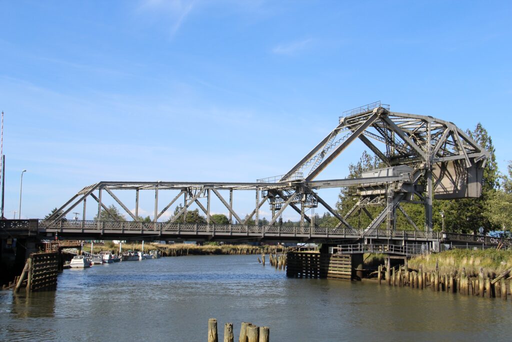
The second sub-type of bascule bridge is the rolling lift. Popularized and patented by William Scherzer, the Scherzer type bridge is distinct in that it does not have a trunnion about which it rotates. Indeed, the point about which it rotates continually changes throughout the opening.
A rolling lift bridge acts much like a rocking chair. While most examples have the counterweight above the deck, it is possible to have them below. In either case, curved elements are built into the steel work of the bridge. A pinion gear engages a track in this curved element. As the pinion turns, the draw span is both pulled shoreward and rotated up at the same time – exactly like a rocking chair.
One of the main advantages of the rolling lift span is that the draw span moves away from the channel while also moving up. This can provide more vertical clearance near the shore than a conventional trunnion type bridge. One disadvantage is that the location of the resultant force of the draw span on the foundation changes depending on how open or how closed the span is. While not overly taxing, this requires careful scrutiny during design of the foundations to ensure all loading conditions are covered.
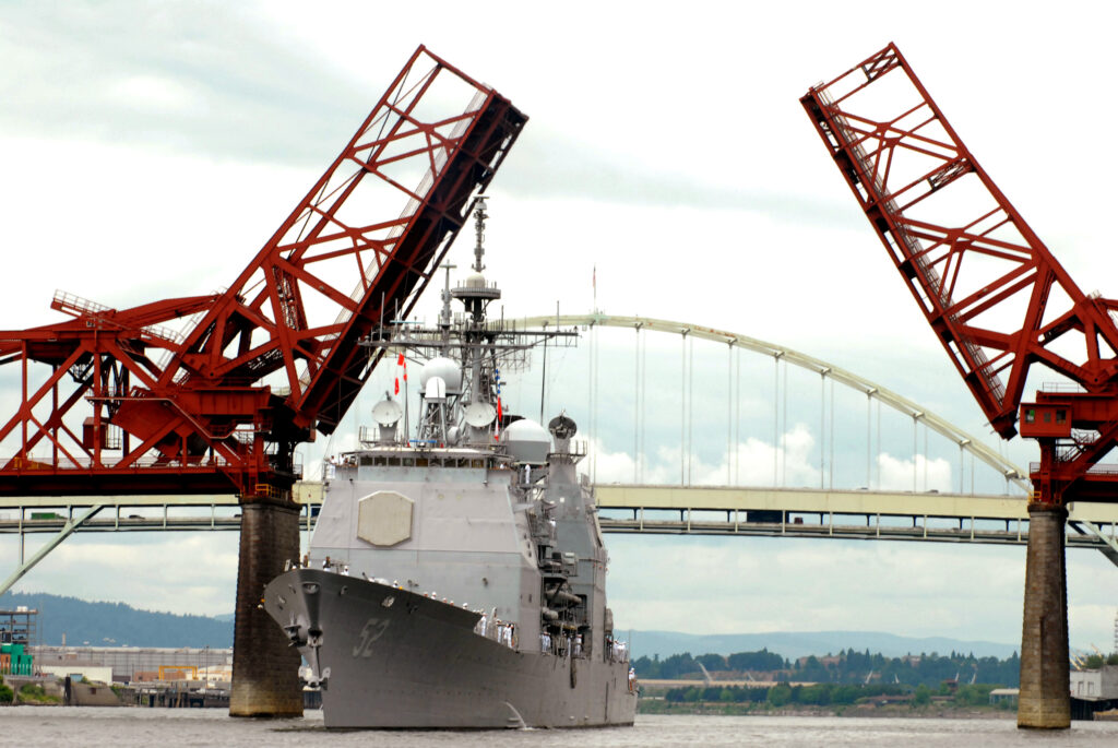
Probably the least common sub-type is the Rall bascule. Invented by Theodor Rall, this sub-type combines some of the features of the Strauss heel trunnion with the rolling lift type. The trunnion about which the span pivots is contained in a Rall wheel, which rolls back as the bridge opens. Only five are known to exist in the United States – three in Chicago, one in Portland and one in Baltimore.
Bascule bridges offer a number of benefits over other types of movable bridges. One of these is economy – which is probably why so many different sub-types were invented and built. Even at the height of their popularity, engineers like Strauss were pushing the limits of the bascule.
A ranked list of bascule bridges by length is difficult to find, however an attempt is made below to identify several notable bascule bridges. Thanks for stopping by – next time we’ll explore the swing bridge type.
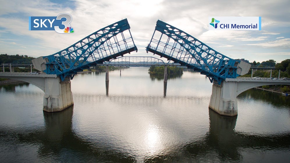
The outright longest bascule bridge in the world is the Chief John Ross Bridge located in Chattanooga, Tennessee. Crossing the Tennessee River, it boasts a bascule span length of 359 feet. It is also the longest rolling lift bascule type. In the closed position, the bridge acts as a three hinge braced rib through arch. Built in 1917 by the Toledo Bridge and Crane company, designed jointly by the Scherzer Rolling Lift Bridge company and John Edwin Greiner.
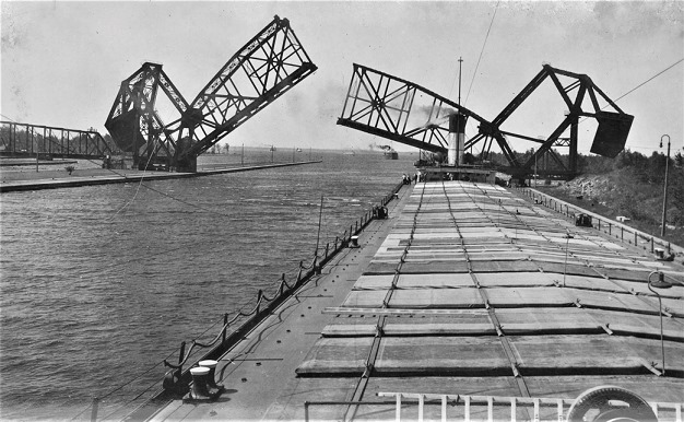
The second longest bascule bridge in the world is the International Railway Bridge located in Sault Ste. Marie, Michigan. Crossing the St. Marys River, it boasts a bascule span length of 336 feet. It is the longest heel trunnion bascule in the world. In the closed position, the bridge acts like a simple span camelback Pennsylvania through truss. Built in 1913 by the Pennsylvania Steel company and designed by the Strauss Bascule Bridge company.
The third longest bascule bridge in the world is the Charles J. Berry Bridge located in Lorain, Ohio. Crossing the Black River, it boasts a bascule span length of 330 feet. It is the longest fixed trunnion type bascule in the world. Each leaf is half of an arched Pratt deck truss. Built in 1940 by the Mount Vernon Bridge Company and designed by Wilbur J. Watson and Associates.
The longest Rall bascule bridge in the world is the Broadway Bridge located in Portland, Oregon. Crossing the Williamette River, it has a bascule span of 278 feet. Built in 1913 by the Union Bridge and Construction Company and designed by Ralph Modjeski
Views: 6478


I need to to thank you for this great read!! I definitely loved every bit of it. I’ve got you saved as a favorite to check out new things you post…
You’re so cool! I don’t suppose I’ve read through a single thing like this before. So good to find somebody with original thoughts on this topic. Seriously.. thank you for starting this up. This website is one thing that’s needed on the web, someone with a little originality!
Greetings from Idaho! I’m bored to death at work so I decided to check out your blog on my iphone during lunch break. I love the knowledge you present here and can’t wait to take a look when I get home. I’m amazed at how quick your blog loaded on my mobile .. I’m not even using WIFI, just 3G .. Anyhow, good blog!