In this edition of TheBridgeGuy, we’ll be answering your questions. Superlatives have always been of interest to humans – which is the best, the strongest, the fastest. The Olympic Games test the very best in human athletics, while the upcoming Super Bowl will determine this season’s best football team. And in this article we’re going to try and answer a couple of superlative questions in the bridge engineering world, so let’s jump into it.
Which bridge design holds the most weight?
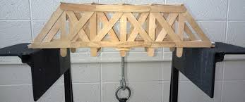
You might remember a class in school where you had to construct a bridge out of popsicle sticks, then load it to failure. In this contest, the group with the bridge that carries the most load before collapse is the winner. The key to this type of competition is the underlying rules. Each bridge would need to span the same distance, be limited on the number of popsicle sticks the final bridge could utilize, and of course the rules would be clear where and how weight would be added.
To be able to answer this question, we need a common frame of reference. Different types of bridges are optimized for different loads to be carried (rail vs. trucks) and the span to be crossed. It really wouldn’t make much sense to use a suspension bridge to cross a 50 foot ravine, just as it would be equally absurd to use a Luten arch to cross the Strait of Messina.
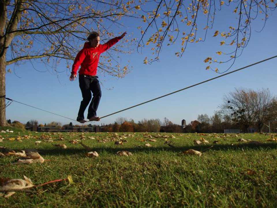
But even with all of that, let’s try to answer the question. Tension has a tendency to increase the stiffness of an element, while compression has a tendency to decrease stiffness. Take a tightrope performer. A rope with low tension would sag so much under the weight of the performer that it would be impossible to remain on the rope. However, when more tension is applied, the amount of sag is reduced, allowing the performer to walk along the rope.
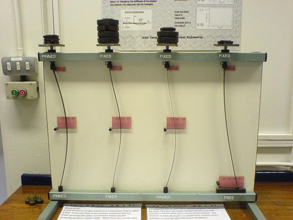
Compression has the reverse effect. A slender 4×4 used to hold up a deck will be easier to displace outward as more load is applied to it. But the length of the compression element is also related to stiffness. This phenomenon is known as buckling. Swiss mathematician Leonhard Euler formulated an expression that relates the critical compression on an element with its effective length. If we brace a compression element sufficiently, we can counteract this reduction in stiffness. This is a powerful concept.
To find the bridge that can carry the most weight, we’ll need to maximize each of these characteristics.
Extremely high strength cables have an inherently high tensile stiffness under zero load. When employed as suspension bridge cables, these cables develop even more stiffness, allowing them to take even more load. When this tendency is exploited to its maximum effect, the same cable can effectively carry a tremendous amount of load. Take the tightrope performer – if a second performer joined them, more tension would be needed to support this second person’s weight.
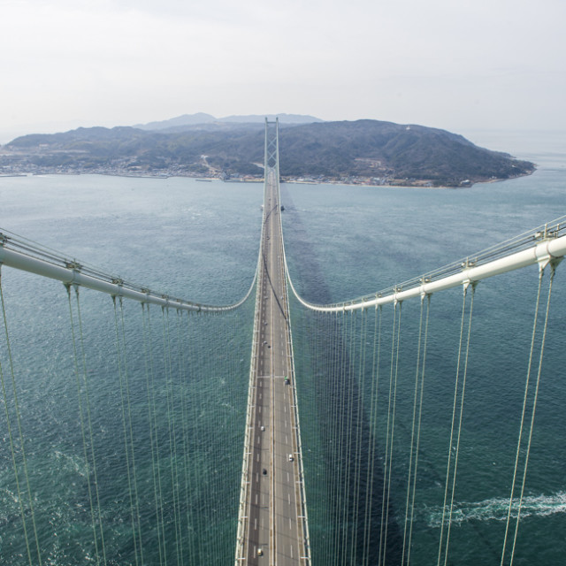
Cable supported bridges exploit this tendency to great effect. But rather than explicitly using cables to carry more weight, engineers use them to span farther. Increased stiffness also aids with reducing uncomfortable deflections. At extreme lengths, even a relatively light weight structure will see large deflections under load. Using cables under large tensions increases the stiffness, which can keep deflections to manageable levels.
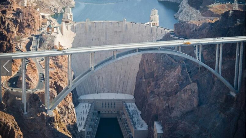
The only way to effectively exploit pure compression is with the use of an arch. By using a material that is already strong in compression, such as concrete, an arch can carry a tremendous amount of load for a given span.
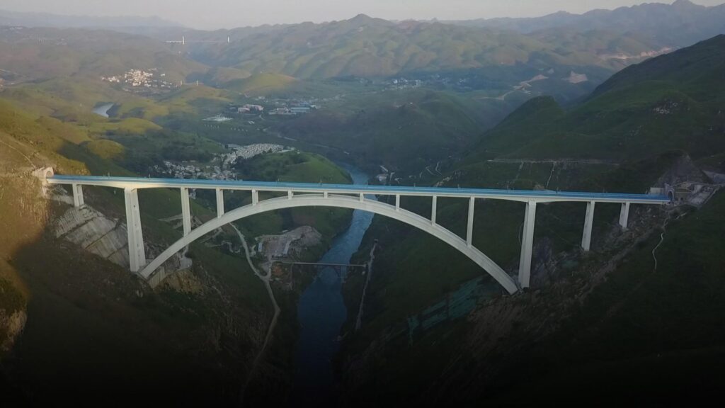
The limit on an arch is the tendency for the arch to buckle laterally if too much load is applied. As we discussed previously, buckling can be mitigated by bracing this tendency to deflect laterally. Sometimes engineers will use two lines of arch members to help brace each other, thus increasing the amount of load that can be carried.
The strength of the arch was known to the Greeks and Romans in ancient times, where it was exploited in buildings and aqueducts to great effect. If you render an arch 360 degrees, you get a dome. The unreinforced masonry dome of the Florence Cathedral is the largest of its type in the world, with the Pantheon dome being the largest of unreinforced concrete, the Superior Dome being the largest of wood and the Kingdome being the largest of reinforced concrete.
So, which bridge design holds the most weight? It depends. But for my money, either a bridge that utilizes steel cables under tension or a concrete arch.
Which bridge design is best?
This is more of philosophical question than an engineering one. By what measure will we consider any particular design the best? Aesthetics, strength, material, initial cost, life cycle cost, the list goes on. For me, a good design optimizes each of these measures for a given location.
But let’s try to narrow down the results. Let’s first think of bridge designs or types that may not be the best.
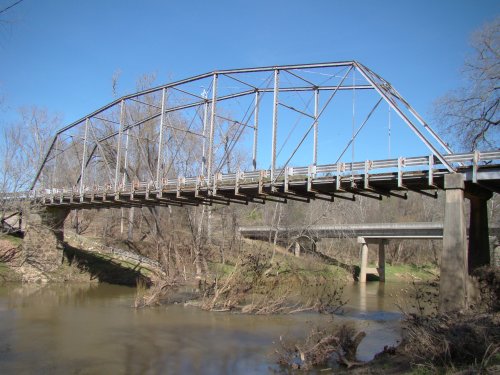
Trusses have had their day. When material was more costly than the labor to construct bridges, trusses offered an advantage. Trusses, particularly determinate trusses, were simple to analyze with a slide rule. By assuming pinned connections, shear and moment in truss members could be ignored and design could be carried out relatively quickly. The advent of computers rendered this advantage obsolete. More complicated structures can span similar distances, requiring less material and less labor, further rendering trusses as obsolete.
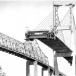
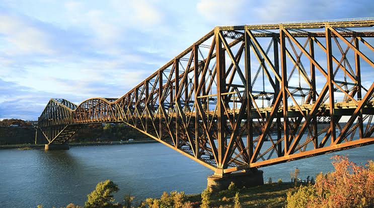
Cantilever bridges also had their day. Really just a type of truss, cantilevers used to be the long span bridge of choice prior to the development of high strength steel wire. Suspension bridges offered a big step forward for span length, reducing the number of piers needed for a given crossing.
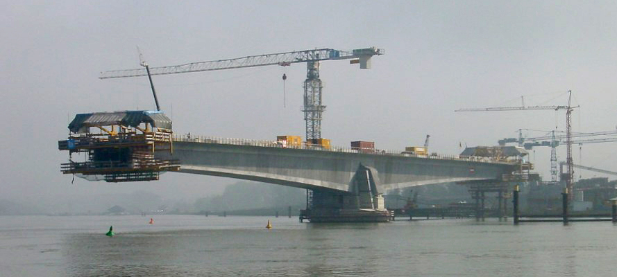
Segmental bridges are a good choice for medium range bridges, however due to the infrastructure and special equipment required to construct them, their use is limited. The balanced cantilever method can be great when spanning over urban obstacles without needing to touch down between piers. The span by span method can largely be replaced by single girders, however when the terrain is difficult span by span may still have an advantage. Segmental is the modern day equivalent to the cantilever bridge.
Now let’s try to think of bridge designs or types that might contend for the best.
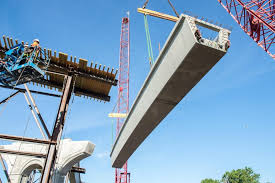
Prestressed concrete girder bridges are fairly common on today’s highway system. Made possible by the invention of prestressed concrete in the 1950’s, the design offered a number of advancements over other bridge types. Prestressing allowed control of stresses in concrete, particularly tension. By directly addressing concrete’s biggest weakness, spans could be increased. Concrete bridges could now be assembled from components built offsite, allowing for speedy construction onsite.
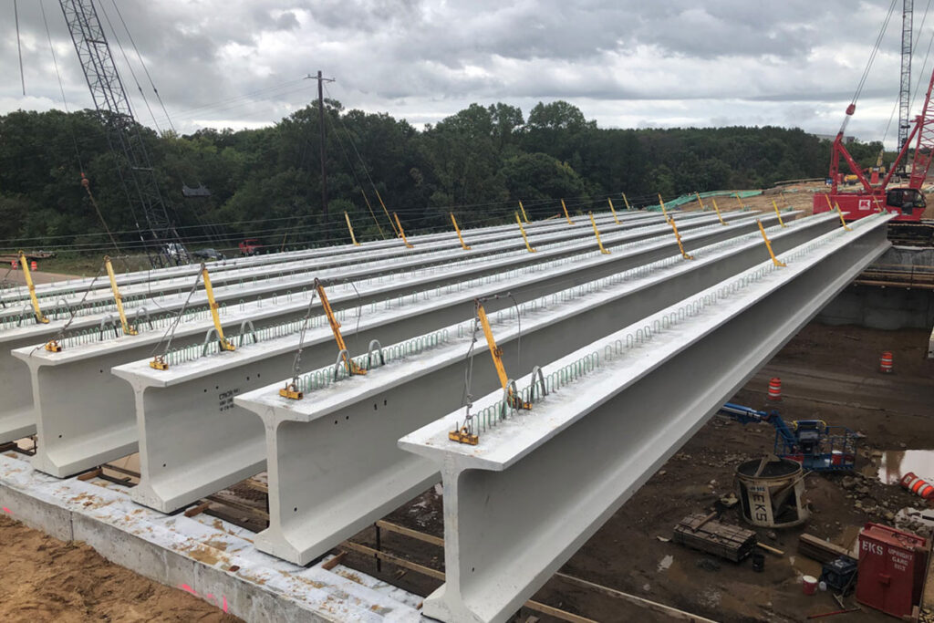
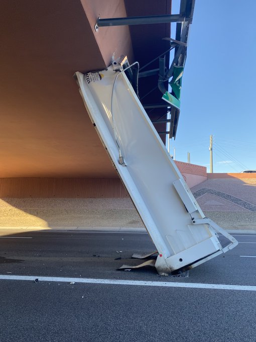
One of the downsides to prestressed girders is that they are extremely sensitive to over height strikes. Since their primary purpose is to carry load in their strong direction, they offer little strength in their weak direction. Another weakness is their weight. As the industry goes to larger 0.7 inch strand, the potential for ever longer span lengths is limited only by the weight of such a girder. Trucking companies must contend with low clearance bridges, tight turning radii and keeping their axles loads to legal maximums. Currently, these constraints limit girder length to about 220 feet.
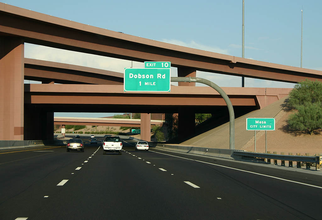
Cast in place concrete box girder bridges are certainly still popular in some locations. These bridge types can be post-tensioned or not. These bridges are somewhat more aesthetically pleasing than an exposed girder bridge. They also offer more design flexibility with respect to geometry than a straight girder bridge. Box girders can be more easily formed to tight curvature compared to conventional precast girder bridges. They are also more resilient to over height strikes due to the presence of the bottom slab.
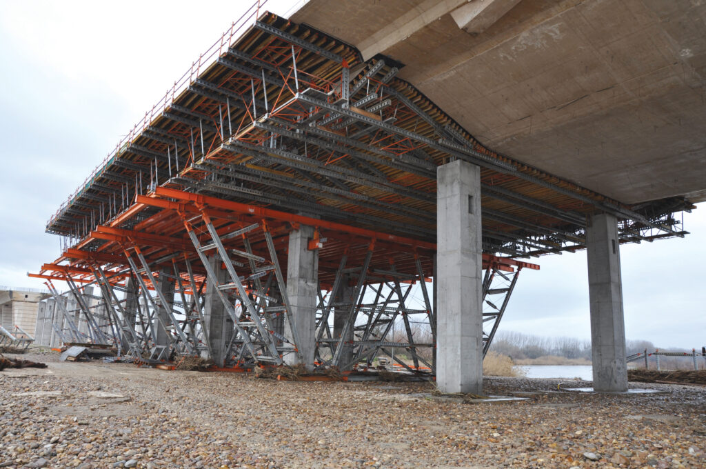
The downside is the need for falsework for construction. To maintain clearance during construction, box girders are often raised so that a higher clearance is needed compared to a girder bridge of similar span length. Their cast in place nature also means they require more time on site for construction. They are also not the most efficient design and require more material than a girder bridge.
Steel plate girders or rolled girder spans are less common, but still have their place in some regions. The advantage of steel is clear – with an economy of material and weight, steel can span farther. Plate girders can also be used with tight horizontal curvature bridges, a distinct advantage over prestressed girders. Steel girders offer an advantage similar to prestressed girders in that they can be fabricated off site, speeding up construction.
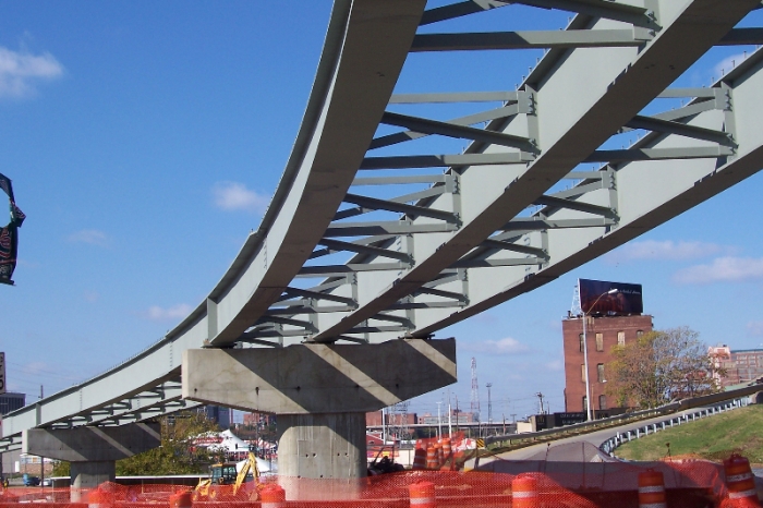
Steel is often more expensive for a similar span in many places. To make it competitive, the designer will normally need to reduce the number of piers and extend span lengths. This can have other consequences such as reduced vertical clearance with a deeper section. Steel girders also suffer the same weakness as prestressed girders in being easily damaged by over height strikes. Steel must also be painted regularly, driving up life cycle costs. This can be mitigated by using weathering steels, though this is usually only feasible in relatively dry climates.
It is worth noting some other less common types here.
Steel box girders are less common, though they could be considered a form of plate girder. These bridges are usually reserved for tightly curved ramps and by their nature are usually non-redundant.
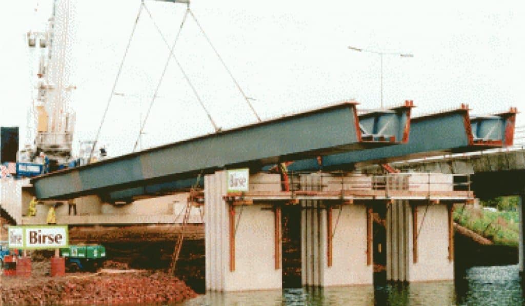
Concrete tub girders, similar to steel box girders, are an off shoot of prestressed girders. Unlike conventional concrete girders, these can be more easily curved.
So which design is best? It is important to stress that each bridge project is unique and has different constraints. Despite the fact that prestressed girders are more common in Washington, this ⁶doesn’t necessarily mean they are the best solution in all situations. They may be the lowest cost option for one site, but not necessarily the best.
Consider the Iron Triangle of Customer Service. From the choices of done quickly, low cost and high quality you may only choose two. But which two?
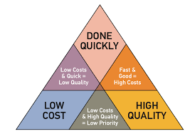
A similar decision befalls us when we try to determine which bridge design is best, though in addition to the three noted above, I would add good aesthetics and low maintenance. Then choose any three.
Any girder bridge will rank high for done quickly. Any girder bridge will rank low for aesthetics and low maintenance. Bird nesting is common in these bridges and they are susceptible to over height strikes.
Steel is going to be low in aesthetics, low maintenance, low cost. To most people, steel is utilitarian and the exposed bolts and jutting stiffeners are an eyesore. This rather rules out any steel bridge as being the best.
Concrete box girders rank high is aesthetics, low maintenance. Are they comparatively that much slower to build? Yes, if properly planned, girders can be fabricated offsite during substructure construction. Box girders cast on site take a more linear schedule, so they will take longer. Some of this can be mitigated by good practices and if so, the differences may only be as much as a month. After girders are set, the deck placement takes much the same amount of time as a box girder bridge.
Box girders built with post-tensioning do have one sneaky advantage over girder bridges. If box girders are post-tensioned, effectively the entire section of the box is subject to compression – the deck, webs and bottom soffit. This means tension stresses are controlled everywhere, meaning the deck will not exhibit cracking to the same degree as a girder bridge will over an intermediate support. I think this fact pushes box girders over the top.
And so I would say the best bridge design overall – amongst contemporary bridge designs – is the box girder. What do you think?
Views: 2161