
In the last edition of TheBridgeGuy, we discussed analysis and how it fits into the structural engineering world. Analysis results in the demand side of the structural engineering inequality. In simple terms, analysis is the problem that must be solved. And now that we’ve defined the problem we can now seek out a solution.

Engineers, by their very nature, are problem solvers. They are distinct from academics who merely muse on the problems before them and deal with the abstract. Engineers live in the real world and are forced to solve real world problems. And they do this by harnessing the power of mathematics and obeying the rules of science. The process of creating these solutions is called design.
Design is the capacity side to the inequality, the part where the engineer has to determine how big or strong or flexible the component needs to be in order to do its job. A number of decisions must be made during design – material selections, theory, code interpretations. At this point we know how the component or system will behave but now we want to ensure that it will behave as predicted.
To do this, engineers use both pictures and words to convey their ideas into reality. After all, this is the real world and whatever the engineer comes up with must somehow get translated into a real thing. Pictures come in the form of plans. Plans are detailed drawings which show dimensions for the thing to be built and how the thing fits together. Enough information should be shown on engineering drawings that anyone who picks them up should be able to recreate them or build from them without additional information. Words are used on both the plans and in the specifications which accompany the plans. These often get specific, itemizing materials to be used, tolerances, colors, treatments, even surface finish or fit type.
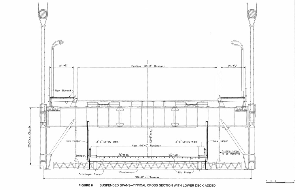
Together the plans and specifications should have everything that a person will need to build whatever it is that the engineer needs. The final product could be a small component or it could be a massive bridge. Both require engineering and both have been designed. Both will be able to handle the demands required of it.
So how is design accomplished in practice? In structural engineering, design is governed by code books. These are established rules for design, intended to help guide the engineer in the best practices of his or her profession. Code books are further broken up by material. Common structural materials have their own design codes and are published by societies dedicated to the material field in question. For example, concrete design is governed by the American Concrete Institute Building Code Requirements for Structural Concrete which is known as ACI 318. Steel design is governed by the American Institute of Steel Construction (AISC) Steel Construction Manual.
One deviation from this is bridges. Bridges are a specialty branch of structural engineering, and as such are given their own code book which encompasses all of the materials needed to design a bridge while also handling analysis. Bridge design is covered by the American Association of State Highway Transportation Officials (AASHTO) Bridge Design Specifications, along with a number of guide specifications which augment the main specifications.
Once the code book that governs has been identified, usually specified by the regulatory agency, the engineer will begin design using basic principles from both experience and education as well as guidance from the code. Design is documented through calculations or computations. This allows other competent professionals to follow the work of the designer and ensure the work was completed accurately. The calculations also act as a reference for development of the design drawings.
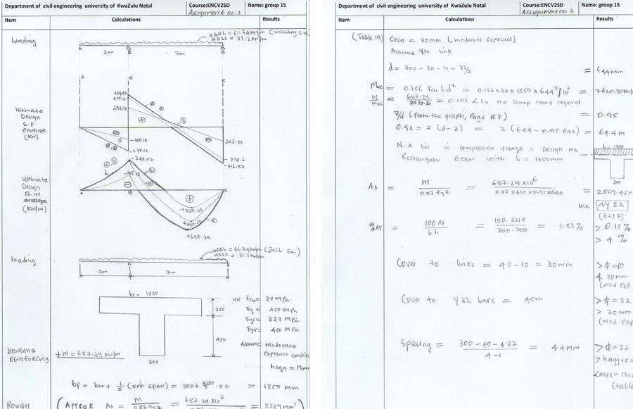
It is important to keep in mind that the engineer’s final product isn’t really the calculations – it is the drawings. Drawings act to translate the engineering language of the calculations to laymen’s terms. These will get acted upon, viewed by others in other trades and eventually will be transformed into something tangible.
This is not to say that calculations may be tossed out after design or omitted altogether. Calculations are often archived as part of the record for a building or bridge. If the unthinkable were to occur, the calculations would be an outside engineer’s glimpse into the mind of the original designer. They would enable an engineer in one decade to have a conversation with an engineer in another.
Not all computations need be strength of material related. Many times, engineers are required to layout geometry to a very high level of accuracy and precision. Elevations will be required if something is to be built at a specific height, sometimes to the hundredth of a foot. Other dimensions may be required to an eighth of an inch. Grout pad elevations are one example. Grout pads are used on bridge piers to support the bearings for prestressed concrete girders. These are determined to a high level of precision and accuracy by using the compressed height of the elastomeric bearing, all to make sure the final profile is smooth.
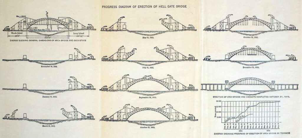
In modern times, means and methods are not typically specified by the engineer. A contractor is usually given the freedom to build what the engineer has designed by whatever means or methods they think best. However, during the design the engineer should at least have one fully thought out method for constructing the structure in mind. This ensures that what the designer is proposing can, in fact, actually be built. In some cases this may even be one of the biggest problems that needs to be solved during the design – how to you build such a thing?
At the beginning of the design process, there may be many questions posed. What material should be used? How long will it be? How tall? How deep? By the end of the design process, all such questions should have an answer. The engineer will know how the structure is to be built, where and using what. And most importantly, the engineer will be able to answer one of the most important questions in structural engineering – is it strong enough?

As the Kingdome was nearing completion in Seattle and the contractor was removing the falsework holding up the massive 200 meter reinforced concrete dome (still holds the record as the largest reinforced concrete dome ever built), many questioned whether the dome would remaining standing on its own. One of the designers, so comfortable in his design, stood below the center disk as the falsework was removed. That may be somewhat apocryphal, but that’s an engineer for you.
Views: 2424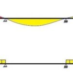


Excellent. Always enjoy reading the articles.