In this edition of The Bridge Guy we’ll be examining the vertical lift bridge type, the last of the three most common modern movable bridge types. In many ways these bridges evolved from the medieval drawbridge just as the bascule bridge did, with a few small span and low lift versions being constructed in Europe back to antiquity. A couple of designs were put forward as early as 1850 but were either never built or lost out to another proposal.
Squire Whipple began designing vertical lift bridges to cross canals in New York in 1872 and the South Halsted Street bridge in Chicago was built in 1892, the first significant vertical lift bridge in the United States. Most of the vertical bridges still standing will date to the period after 1908, when it seems the vertical lift really hit its stride.
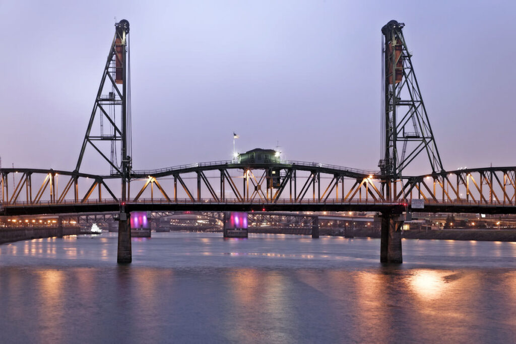
The oldest vertical lift bridge still in operation in the United States is the Hawthorne Bridge (1910) located in Portland, Oregon. Designed by the firm Waddell & Harrington, the bridge is a series of Parker trusses (camelback) and cost $511,000 to build. The bridge is 1,382 feet long and includes a 244 foot vertical lift span which can be raised up to 110 feet to allow vessels to pass on the Willamette River. It carries Hawthorne Boulevard and was named after J.C. Hawthorne, co-founder of Oregon’s first mental hospital.
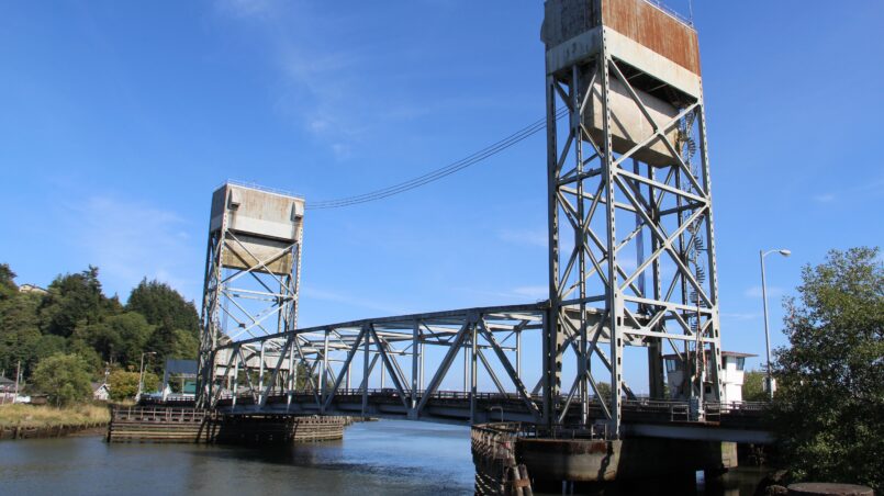
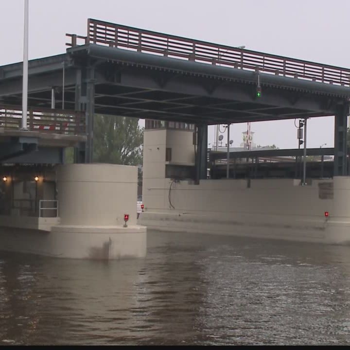
As its name suggests, a vertical lift bridge opens by raising the moving span vertically to improve vertical clearance. It is the only type of movable bridge which does not allow for “infinite” vertical clearance when open in the navigation channel, its most significant disadvantage. John Alexander Low Waddell, who founded the company that was to become Hardesty & Hanover in 1887, invented the first modern design for a vertical lift bridge in the early 1890’s.
Vertical lift bridges, while not as broad a category as bascule bridges, have modernized over the years. Early versions made extensive use of steel trusses, not only in the superstructure but also in the towers used to raise the bridge. More recent innovations to the vertical lift include the use of concrete towers, orthotropic steel boxes and even some girder designs.
Upfront cost for a vertical lift bridge is generally on par with swing and bascule types. However, as H.E. Pulver notes in Movable and Long-Span Steel Bridges (1924), bridges with long spans and low lifts are generally cheaper than similar bascule and swing bridges. Short spans with high lifts will be more expensive.
Another advantage of the vertical lift bridge is its simplicity to construct. A vertical lift is like a railroad car traveling vertically, large wheels are guided by tracks on the tower and trains have been used successfully for more than 100 years.
Vertical lift bridges are counterweighted, much like bascule bridges. However, a bascule bridge relies on balancing the moments around the pivot point whereas vertical lifts need only balance the load of the span itself. This means that vertical lift counterweights can be significantly lighter than a bascule counterweight for a similar span. Being lighter, the individual components are lighter – such as trunnion bearings – which reduces costs, both upfront and long term.
And because only the total load of the lift span need be counterweighted, resulting in a smaller counterweight, the lift span can be heavier than that of a similar length bascule. This means the lift span can handle more live load. And being able to accommodate heavier loads is often why vertical lift is the go-to movable bridge on longer railroad crossings.
When longer spans are required, a vertical lift bridge is often the more economical choice. There is less interference with the channel opening than with a swing bridge. Vessels may approach much closer to the bridge during opening than a swing bridge, reducing opening times. Width is not generally an issue, where a larger pivot pier would be required in the case of a swing bridge. Vertical lift bridges can be placed next to one another in close proximity without fouling one another.
The potential damage that could be inflicted by a vessel collision is probably less with a vertical lift bridge. Due to the simplicity of its design, any damage could probably be fixed in less time on a vertical lift bridge. If the pivot pier of swing bridge were impacted, and all of the weight of the swing span were on that pier, the consequences could be more dire. The risk of hitting and knocking a bascule leaf transversely could be extremely detrimental to the bearings and drive machinery and would likely necessitate costly and time consuming repairs.
There are also some disadvantages to vertical lift bridges. One of the most significant is the limit on vertical clearance, even when open. Another is that a barrier will be required at both ends of the bridge for safety reasons to prevent vehicles from inadvertently entering the navigation channel during an opening. Swing bridges have a similar issue.
Providing smooth operation of the lift span requires load equalization. Uneven lifting, however the span is lifted, can cause binding and potential for damage. While bascule bridges can also be prone to this, bascule leaves only have two points of movement where a vertical lift span has four.
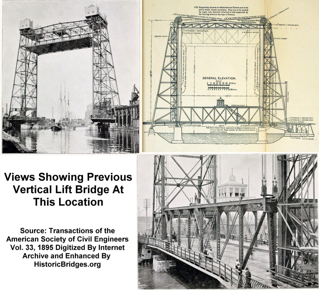
All vertical lift bridges have some common characteristics. Cables that are connected to the lift span run up and over sheaves and down to a large counterweight. When the span is down, the sheaves will generally only support the weight of the counterweight. When the span is raised, sheaves support the weight of the span and the counterweight. Dead load of the span and live load will be taken by the seat bearings.
So how do they work? There are three main types of vertical lift bridge – span drive, tower drive and tower-less.
Tower drives operate in a very similar manner to modern elevators. In these bridges, the counterweight cables are used to both raise the span and balance it. To turn the sheaves, the prime mover may independently drive a set of tower sheaves or they may independently drive the left or right sheaves. In either setup, drive controls are critical to make sure both sides lift evenly.
Rope span drives use a hoist drum mounted on the lift span itself. This drum takes in and pays out the haul ropes through a pulley system. There is both an uphaul and downhaul rope system to operate the span. The haul system is separate from the counterweight ropes which only act to hold the span balanced and in equilibrium. In rope drive systems, it is important that the drive ropes are equalized to ensure the span lifts evenly.
Another type of span drive is rack and pinion span drives. Instead of using haul ropes, pinions mounted to the lift span engage a rack mounted to the tower. As the pinion turns, the span is raised. In this type, motor controls will ensure even lifting.
A third type of lift bridge is the tower-less type, also known as a table bridge. This rare type of bridge is only suitable for low lifts. In this type the counterweights and sheaves are still used, but are hidden from view. Hydraulic cylinders are used to lift the bridge, rather than mechanical/electrical means. An example of this type of bridge is the 52 foot long lift span of the St. Paul Avenue bridge crossing the Milwaukee River.
Rope drives require periodic check and adjustment of the haul ropes to ensure that equal tension is achieved. Since directly checking tension is difficult, rope length is checked instead. These checks and adjustments can be maintenance intensive, requiring a significant amount of labor to accomplish. However, a properly adjusted rope drive will experience the least amount of binding.
Tower drive adjustment is generally more complicated but the system is simpler. Some form of mechanical adjustment may be possible, but in general the motor controls will be controlled by logic control. This means less maintenance is needed to keep the bridge adjusted properly. Even with proper adjustment and control, this type of bridge will be the most susceptible to binding.
A ranked list of vertical lift bridges by length is difficult to find, however an attempt is made below to identify a couple of notable vertical lift bridges.
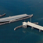
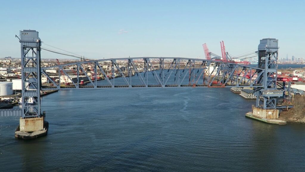
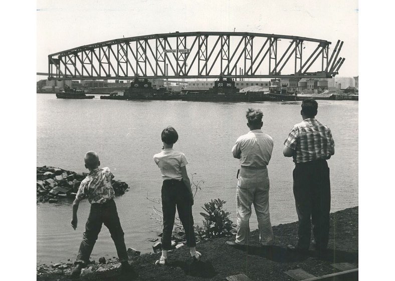
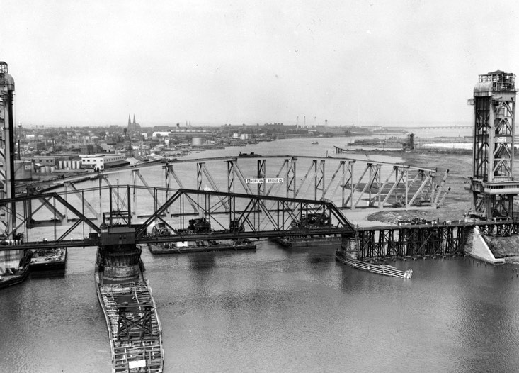
The longest vertical lift bridge in the world is the Arthur Kill Bridge located between Elizabethport, New Jersey and Staten Island, New York. Crossing the Arthur Kill, a tidal strait which acts as part of the state boundary between New York and New Jersey, the bridge carries a single rail track – mainly to transport garbage out of New York. Built in 1959, the bridge features two towers that are 215 feet tall and a 558 foot long camelback truss lift span. The lift span clears mean high water by 31 feet in the down position and clears by 135 feet in the raised position. Like many movable rail bridges, the bridge remains in the raised position most of the time and is only lowered when a train needs to pass. The U.S. Coast Guard currently limits the time the bridge is lowered to two 15 minute periods a day.
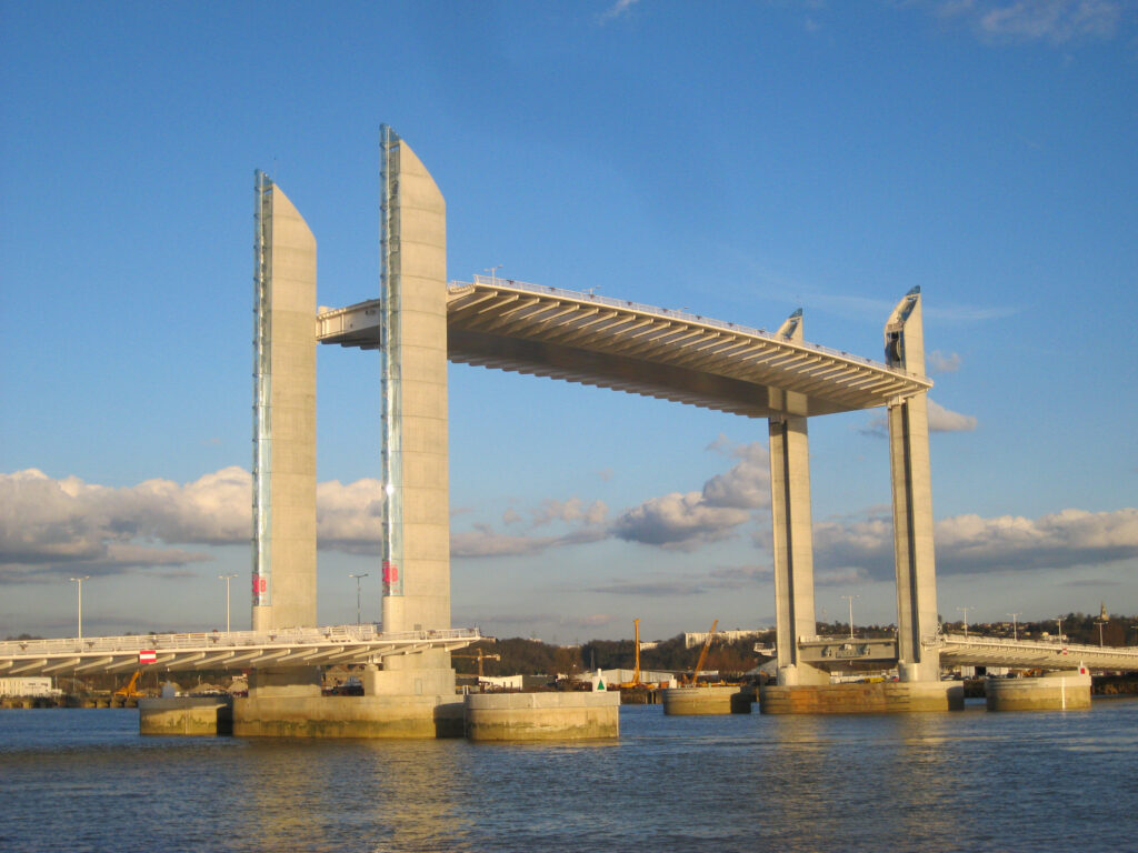
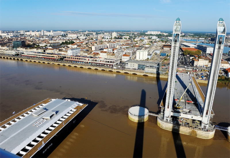
The longest vertical lift bridge in Europe is the Pont Jacques Chaban-Delmas in Bordeaux, France. Crossing the Garonne River, the bridge is a modern interpretation of the vertical lift concept. The bridge features a steel box design with steel girder wings to carry traffic, pedestrians and can accommodate two future light rail lines. Weighing is a 2,900 tons, the lift span is 361 feet long and can be raised nearly as high to allow ships to pass. Four independent concrete pylons stand at each corner of the span, enclosing the counterweights. A tower drive system pays out and hauls in the counterweight cables to operate the span. Designed by Hardesty & Hanover, the bridge was built in 2013 and opened by President Hollande.