History was made in Seattle on March 28, 2026 when light rail service began across Lake Washington. This date marked the culmination of a nearly 9 year long project to extend light rail service from Seattle to the eastside of the lake. And to make that possible, engineers would have to do what no one has ever done before – run a train across a floating bridge. And in this edition of TheBridgeGuy, we’ll examine the challenges they faced and how exactly they made light rail across a floating bridge a reality.
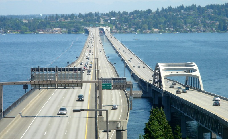
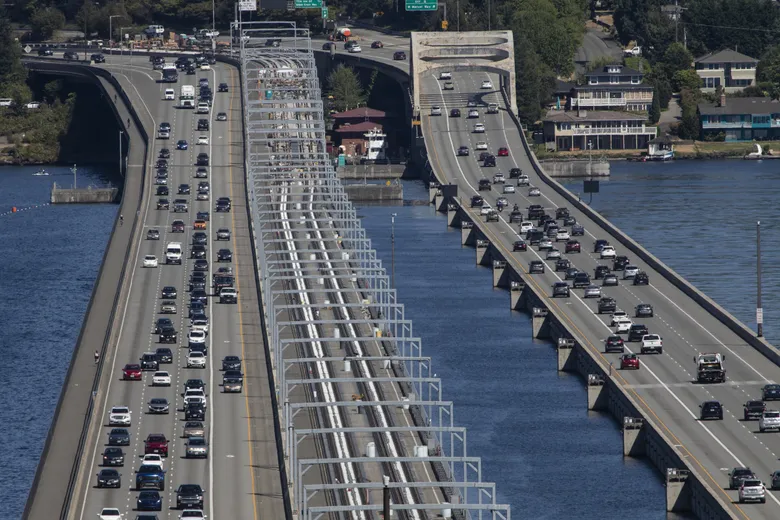
The bridge in question is the Homer M. Hadley Memorial Bridge, one of four floating bridges owned by the Washington State Department of Transportation (WSDOT). And among those four bridges, it is currently the second oldest, the only bridge that has not yet been replaced and it is the fifth longest floating bridge in the world.
At the time it was built, it was unique in that it was the first floating bridge to utilize a 75 foot wide pontoon. It was made wider still by adding deck cantilevers to both sides, bringing its overall width to 106’-2”, the widest floating bridge in the world from 1989 until it was surpassed by the new Evergreen Point Bridge in 2016.
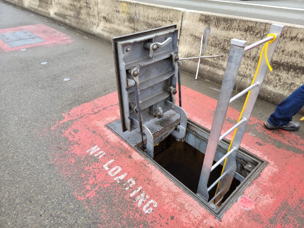
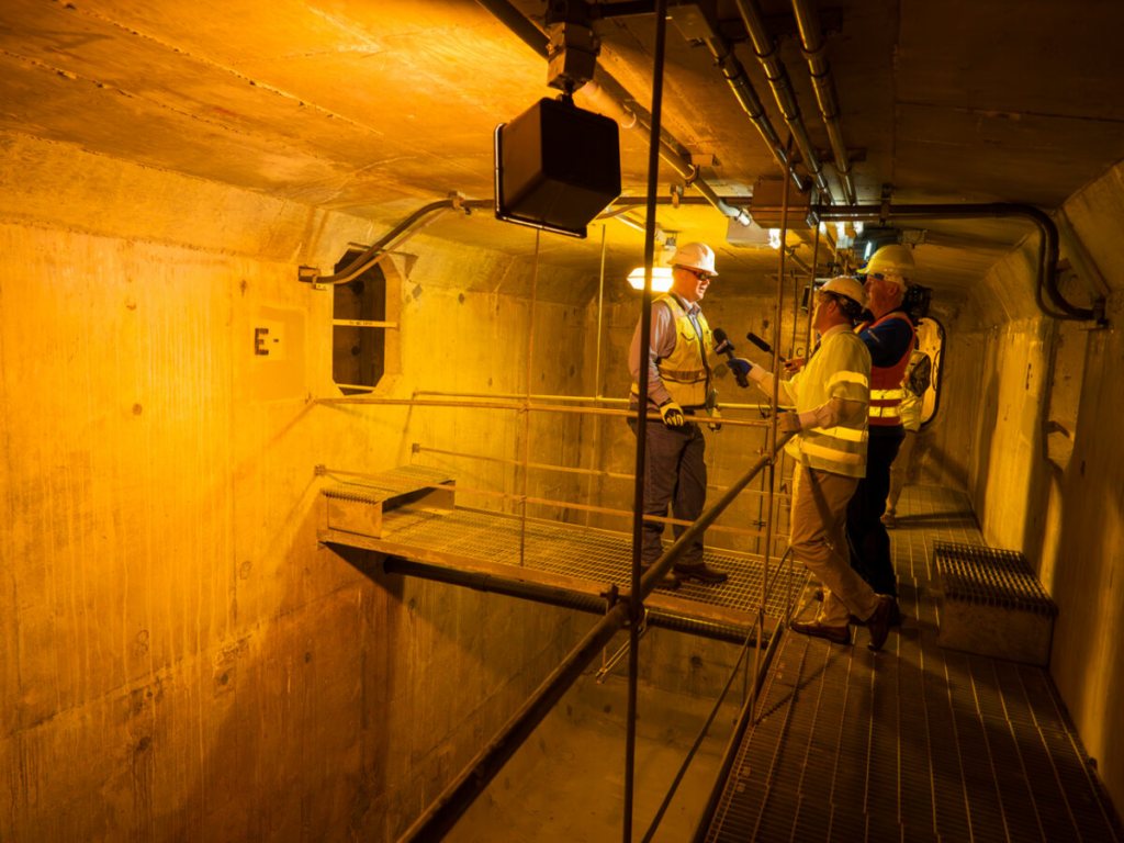
On most floating bridges, access hatches are located near the exterior walls for ease of access under live traffic – since this is typically where the shoulder is located. Not so on Homer Hadley. With the addition of the cantilevers, the shoulders were now located outboard of the first exterior cell, meaning the access hatches needed to be located elsewhere. Designers decided to place these hatches near the median traffic barrier that separates the center roadway from westbound traffic. As a result, upon entering the bridge you enter into the first interior cell instead of the exterior cell.
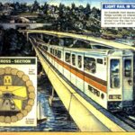
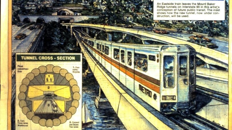
It had to be this wide in order to accommodate the extension of Interstate 90 from Bellevue to Seattle. The bridge would carry dedicated westbound lanes toward Seattle on the north side of the bridge, while the south side (known as the center roadway) would carry two reversible express lanes. It would also include a shared use pathway for pedestrians and bicycles on the north side.
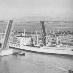
Known as the Third Lake Washington Bridge during its development, the design was based on the Evergreen Point Bridge, at the time the newest and most modern floating bridge WSDOT owned. Prior to it opening, the route between Seattle and Mercer Island was carried on the four lane undivided Lacey V. Murrow Memorial Bridge. The undivided nature of the bridge meant it did not meet Interstate highway standards and the reversible lanes on the bridge were a notorious danger to motorists. To improve safety and bring the corridor up to interstate standards, an additional parallel bridge would be necessary and improvements would be required to the existing bridge.
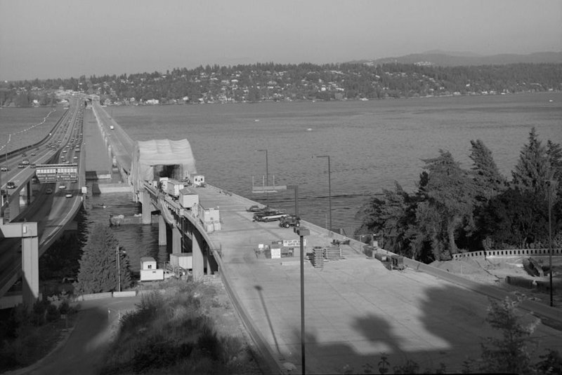
These improvements meant that the Murrow bridge would need to be substantially renovated. And while it was being renovated, eastbound traffic would be temporarily carried by the new Third Lake Bridge. But there was also another agreement being negotiated. In a memorandum of agreement between State Highways, Metro Transit and local governments that was signed in 1976, the center roadway was to be utilized for transit and potential future conversion to a fixed guideway system.
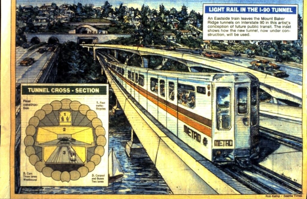
This meant that in addition to conventional highway loading, the new Third Lake Bridge would need to be designed for transit of some kind, though what exactly that transit was to be was certainly unknown by the bridge designers. The transit design that engineers settled on was Bus Rapid Transit (BRT), essentially dedicated high speed buses. Despite the agreement and the design decisions made up to that point, Seattle declined to move forward with transit funding in the 1970s and further BRT planning was scrapped in favor of express lanes for commuters.
Fast forward to 2005 and talk of conversion to light rail was picking up steam. WSDOT conducted a full scale load test using 65 foot long flatbed trucks filled with concrete blocks to simulate the weight of the proposed trains. WSDOT concluded that the bridge could take the weight of light rail if certain modifications were made. There was also the issue of the rail crossing the enormous modular expansion joints at each end of the bridge. Sound Transit agreed to foot the bill for these upgrades.
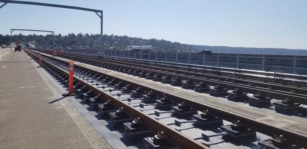
On June 5, 2017, after adding additional HOV lanes to each direction of I-90 mainline, the center roadway was closed permanently to vehicular traffic in order to begin work on light rail across the bridge. But this wasn’t as simple as building some rail on top of the bridge.
One of the critical items identified in a report commissioned by Sound Transit in 2008 was the substantial weight additions to the bridge. The tracks would be elevated on concrete plinths, both the track and plinths would be substantial weight additions alone. To power the trains, overhead catenary power lines would be added, supported by poles along the bridge’s length. In addition to all of that is the substantial conduit and wiring infrastructure necessary to support light rail.
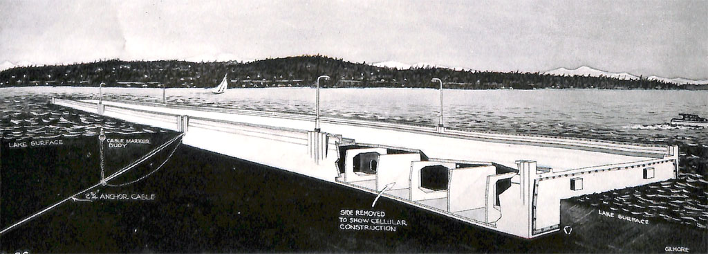
The bridge pontoons were designed and built in two phases. The older Phase I pontoons (labelled Pontoons F through O) primarily carry the low-rise portion of the bridge, where traffic drives directly on the pontoons. These pontoons feature a single cableway track which the north and south anchor cables attach to and are conventionally bolted together.
The newer Phase II pontoons (Pontoons A through E, P and R) carry the high-rise portions of the bridge at the west and east ends of the floating portion where the roadway rises off the pontoon deck. These pontoons feature offset cableways and post-tensioning tendons are used for joining them instead of bolts.
Because the Phase II pontoons are post-tensioned together, these portions of the bridge were found to be adequate for the increased loading of light rail. The Phase I pontoons were found to be lacking in strength. Since pontoons serve as the primary lateral resistant elements on a floating bridge, having enough strength to withstand the combined loading of the train and a windstorm was considered vital.
Pontoons act as large box girder hulls. Sensitive to wind and wave loading, the Homer Hadley bridge is shielded from the stronger southerly storms by the Murrow Bridge to the south. But the less severe northerly storms have a longer fetch and there is no shield on the north side. This northerly storm combined with a train on the extreme south cantilever makes for significant torsion plus tension on the hull.
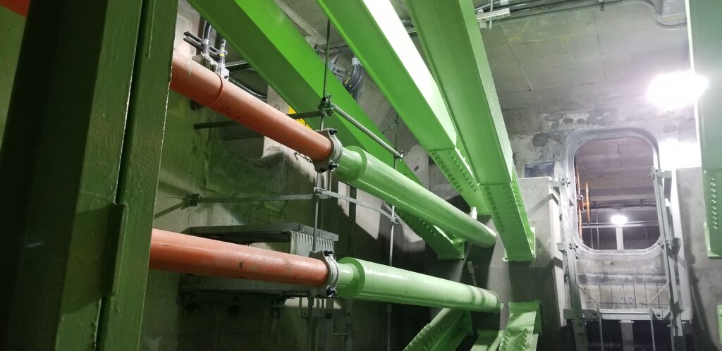
To help resist these increased stresses on the hull, external post-tensioning was recommended for the Phase I pontoons. This was not the first time that a floating bridge had been strengthened by post-tensioning. The old Evergreen Point Bridge fixed pontoons were strengthened this way in the mid 1990’s. At the time, it was the longest run of PT in the world, with the elongation required measured in feet rather than inches. The strengthening on Homer Hadley, which was much longer than Evergreen Point, would surpass this record.
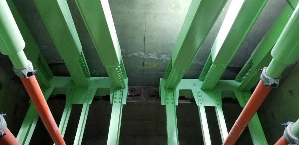
But the strengthening didn’t just involve the PT tendons. To anchor such a force, substantial steel frames needed to be added to several cells in Pontoons E and P in order to distribute the compressive force of the PT into the pontoon. Not only are these frames heavy, they also needed to be installed in pieces small enough to fit through the two access hatches located near the middle of each pontoon. Workers then needed to devise a way to get those heavy steel pieces down through the hatch, then transport it along metal catwalks to the end cells of each pontoon, a distance of about 180 feet.
In the end, the external PT only added a few hundred pounds per square inch of extra compression to the hull. But it added a bit of extra weight to the bridge.
A floating bridge supports the vertical load applied to it by Archimedes’ Principle, also known as buoyancy. For a floating structure, the weight of the structure is equal to the weight of water displaced by the structure. As weight is added, and no additional modifications are made to the width of the pontoons, the only way that equilibrium can be maintained is by increasing the draft. In other words, the bridge sits lower in the water. This can negatively affect the stability of the bridge in windstorms, very similar to a ship.
To mitigate these weight additions, engineers recommended the removal of substantial portions of the bridge’s concrete traffic barrier on the south side. This was replaced by cable railing. When the bridge was built, a concrete overlay was applied to the surface of the pontoons. This overlay was ground off. In order to ensure each pontoon sat level in the water, gravel ballast was added to ensure even trim. Workers removed much of the ballast on the bridge, with any ballast remaining being on the north side of the bridge to help compensate for the off-center loading of light rail.
Overall, even with the mitigations, the bridge sits about 2-3 inches lower in the water now than it did before light rail was added.
Using electricity to power the trains also raised concerns over stray current. On a typical land based railroad, any electricity that finds it way from the power lines, to the trains, then to the tracks is usually routed to ground by grounding cables. On a floating bridge, the shortest path to ground is through the anchor cables. The anchor cables are already protected by impressed current cathodic protection, essentially a small amount of current is purposefully introduced to the cables to counteract the natural process of galvanic corrosion.
However, too much current, either from intentional cathodic protection or from accidental stray current, can cause problems for the anchor cables. To much current can cause hydrogen embrittlement of high strength steel. This causes hydrogen gas to be released from the steel, causing the steel to lose its ductile properties. Ductile cables are essential to resisting the storm loading that we get in the Pacific Northwest. To protect against stray current, a revised and more complicated cathodic protection system was installed along with more thought given to grounding lines that take current back to shore.
There were also a number of problems identified with operating trains on a floating bridge.
On Homer Hadley, due to the unique way that the bridge was designed, the drainage for the roadways is in the center roadway adjacent to the median traffic barrier. During snow events, common practice for WSDOT was to plow snow to the center roadway and let it pile up there. As the snow melted, it would drain from the deck and into the lake.
With the presence of trains, snow accumulation and storage became an issue. Snow can no longer be plowed to the center roadway, as that would foul the tracks. Instead, snow is now plowed to the 10 foot maintenance path next to the tracks. But because of weight issues, once a certain threshold of snow had been surpassed, the remaining snow is plowed to the north side and onto the pedestrian path. A special snow blower has been purchased to blow the accumulated snow into the lake.
Traction of the trains was also an issue. In general, trains should be kept high and flat or low and flat. They do not like to climb grades. On Homer Hadley, every time a train crosses the bridge, it descends the high-rise to the roadway pontoons, then climbs the opposite high-rise toward one of the tunnels. This grade fluctuates by 2 feet of elevation change twice every year, being steepest in the winter months when the lake water level is lowest. To climb the high-rises, sand is used to provide traction. This sand is blown at the wheels, then falls to the deck of the bridge. Over time this sand will accumulate, causing additional maintenance issues. It is unclear what the solution to this problem will be.
And then there is the issue of rail alignment. All floating bridges use two modular joints at each high-rise. The smaller of these joints is located at the top of the transition spans, the spans which connect the fixed land side to the floating side of the bridge. These smaller joints accommodate thermal expansion of the approach structures and the transition span, while also accommodating pitch motion as the water in the lake rises and falls.
The larger modular joint at the bottom of the transition span is a swivel joint. This joint accommodates the large thermal movement of the floating portion of the bridge, but also accommodates pitch motion from water level changes and yaw motions from lateral windstorm loads.
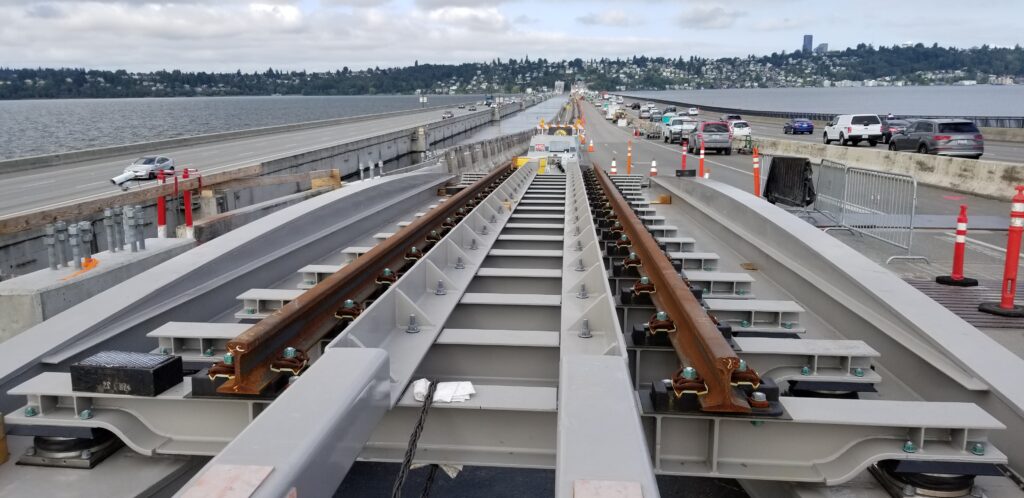
These two modular joints are made up of a series of transverse bars, bars which are constantly moving from hour to hour, minute to minute of every day. This poses a significant challenge for trains running on rails. The rails must remain in alignment at all times in order for trains to pass safely, but the floating bridge also needs to be able to move freely. To solve this problem, engineers devised a novel solution – the track bridge.
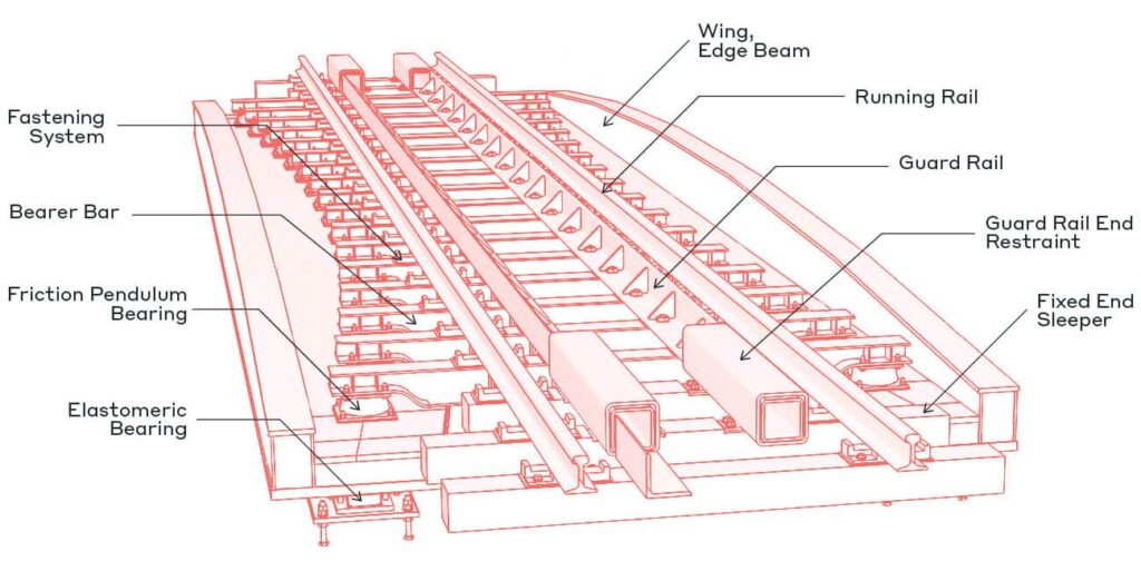
The track bridge is a structure that supports the rails while also maintaining their alignment. This is done by using a series of triple pendulum bearings, which effectively decouples the pitch, yaw and expansion motions of the bridge from the stationary train rails. The track bridge is designed to span these massive joints, ensuring no load is transmitted to the modular joints.
On the downside, it was observed early on that the increased friction of the track bridges on the south side did restrict the motion of the bridge. On a hot day for example, the modular joints were noticeably narrower on the north side compared to the south side. Whether these track bridges “loosen” up over time is an open question, as is their response to a significant windstorm event. But it begs the question, is there a difference between real life boundary conditions and the theoretical? Is anything really friction free?
In the short term, it appears that light rail on a floating bridge has been a triumph of engineering. It is certainly a god-send for commuters looking to ditch their cars as they travel more conveniently across Lake Washington. But what about the long term ramifications? Is anyone looking out for the interests of the bridge?
Now that revenue trains are running, they will never stop, except in the wee hours when Sound Transit service terminates for the evening. Current rules do not permit people to be within a certain distance of the tracks while trains are operating. The hatches for access inside the pontoons are located about 10 feet from the tracks. This means that regular maintenance of the bridge for activities like adjusting cable tension, servicing the cathodic protection systems, and other routine maintenance cannot occur during train operating hours.
Future contract work on this bridge will be significantly impacted. Routine work to replace anchor cables, thankfully done prior to train operations, will now be more complex. Replacing hatches and upgrading the deficient leak detection system will also be more expensive due to these restrictions.
And of course, there is the big unknown surrounding the impact of running such heavy trains on the bridge long term. How many storms can the hull endure combined with the heavy and eccentric train loading? Only time will tell.
Views: 716