A great piece of design begins with great preparation. A painter will likely start his masterpiece by sketching out the subject, working out the proportions and deciding how to fill the canvas. A writer may start with an outline, developing plot, character and themes before proceeding into actually writing the prose. The key is knowing where you’re going. Sure, a lot of twists and turns will happen on the way – that’s how design works – but the roadmap and the destination have already been decided.

The same goes for bridge design. A certain amount of preliminary engineering goes into every bridge, large or small, before plans are developed and before any ground is broken. And it is perhaps this preliminary engineering phase that is most important to the success of a bridge project. After all, a lot of decisions have to be made here. Where should the bridge go? How long should it be? How many piers are needed? What does it need to carry? Once it is built, how do we maintain it?
Many engineers will reckon the various design phases of a bridge project by percentages. It is important to know that these have largely nothing to do with how far along in design the designers are. Engineers are perfectionists by nature, and without milestones to work towards the project may never be completed. Typical milestones are 10%, 30%, 60%, 90% and 100%.
The first phase in a bridge’s life is the Type, Size and Location (TS&L) phase. This will typically result in a design that is about 10% along, but this will vary with the size of the project. A TS&L phase report will provide a range of solutions to a bridge problem, including multiple superstructure types, pier placements and substructure types. It will also include a very rough estimate on the cost of the structure for budgeting purposes. At the end of this phase, the client should have a good idea on what a bridge could look like, but there is still some work to be done in determining the final layout that is ready for final design.
A formal TS&L phase may not be required by the client for a variety of reasons, but in general the process occurs whether there is a formal TS&L phase or not. After the TS&L, the design may be advanced well beyond 10%, especially on larger projects where a certain amount of risk exists. On some projects, the TS&L phase may have narrowed down the solutions to only one viable type or location. Essentially, the design has now advanced nearer to 30%. On others, a wide range of options will require further deliberation in which case the progress is nearer the 10% mark.
At the TS&L phase, geotechnical and hydraulic information may not be available or is very basic. Because of this, a bridge proposal will be based on other similar projects and good engineering judgement. The estimate at this stage will be conservative, owing to the range of unknowns at this point in the design. Essentially, there should be enough information provided to inform the client enough to be able to provide the go or no-go decision needed to proceed with the project.
The second phase may be referred to by different names, but it is essentially the Preliminary Plan phase. This will result in a design which is about 30% along and differs from the TS&L in that all of the bridge particulars, with the exception of the substructure, are known and laid out. The preliminary plan for a bridge will decide upon the final geometry of the bridge. Number of lanes, shoulder widths, sidewalks and barrier will all be decided upon in this phase. The superstructure type will be decided, along with clearances, profiles, curves and final ground lines.
As you can imagine, a certain amount of engineering goes into this phase. For example, the selection of the superstructure type will be based off of preliminary stress design of girders in the absence of good rules of thumb. This need only determine whether a particular depth and number of girders can carry the required loads for a particular span arrangement. The actual detailed design will be handled later on. This requires good engineering judgment, which is why preliminary design is often left to more experienced engineers.
Design codes and good rules of thumb can help inform the preliminary designer and are usually quick and reasonably accurate. These rules of thumb help to control live load deflections, where excessive deflections can unnerve users as well as ensuring that strength and service limits are maintained. The span to depth ratio will vary, but good results are achieved by targeting a ratio of 25 by using composite depth of the superstructure.
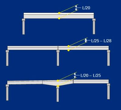
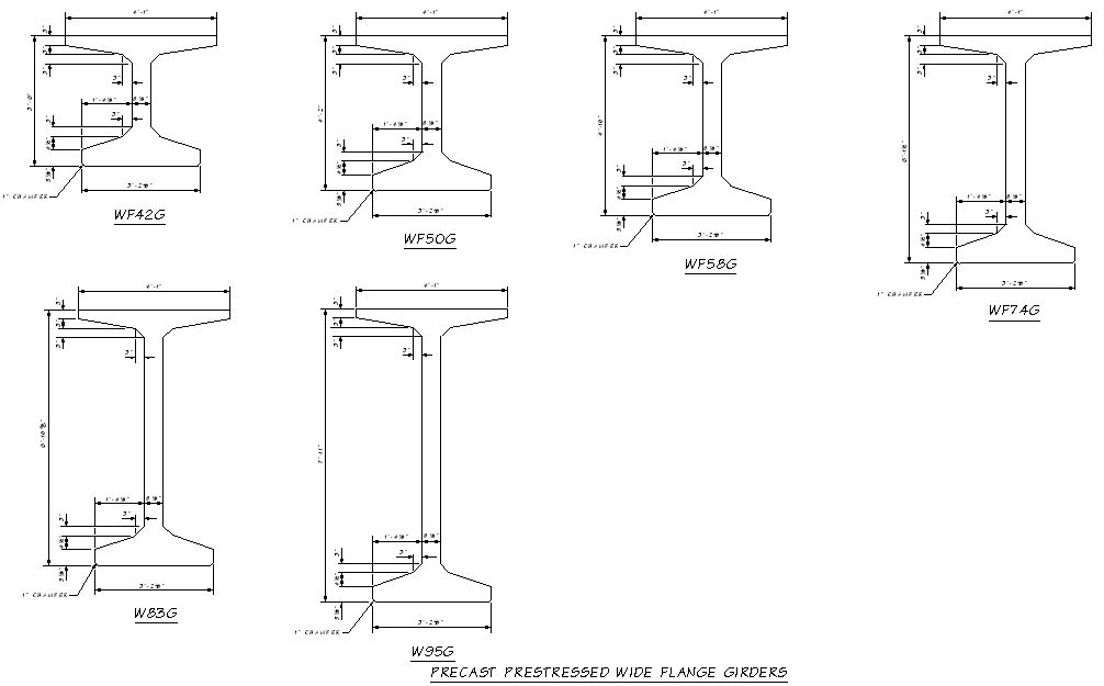
The number of girder lines to be used will depend on how far above 25 you go. The higher the ratio, the more lines that will typically be needed. Larger girder spacings will require a thicker deck to span the distance. Prestressed concrete girders typically use standard form liners which are reused to help reduce fabrication costs. As such, these girders are usually produced with standard details and standard dimensions which make selection of the correct number and type during preliminary design much more important. Steel plate girders, by their very nature, are much more adaptable to load requirements.
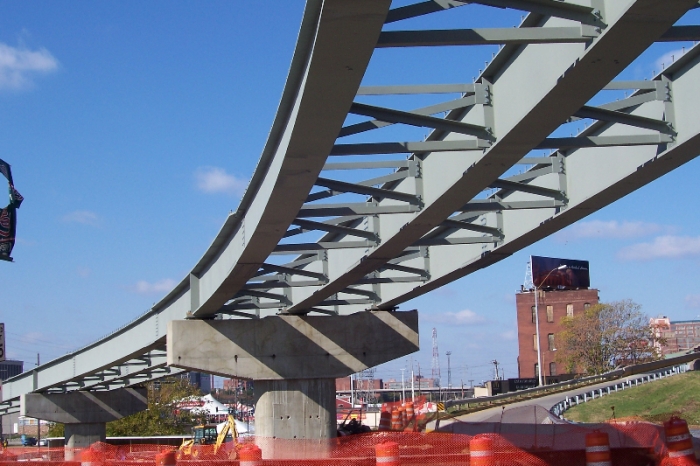
In parts of the country where steel is more expensive to fabricate than prestressed concrete girders, priority is given to reducing the number of girder lines and increasing flange plates accordingly. Since more than half of the steel in a plate girder is in the web, reducing girder lines has the most bang for buck in reducing the quantity of steel on a bridge. This is less important where good concrete is not abundant and steel is relatively cheap compared to prestressed concrete.
Clearances are another important aspect to a preliminary plan. Many jurisdictions have minimum clearance requirements that govern road and highway design. While horizontal clearances are important, these are usually determined by the civil engineers who layout the roads long before the structural engineer becomes involved. Vertical clearances are much more important to the structural engineer, as they will determine the method of construction that can be used and the susceptibility of being struck by overheight loads.
Roadway profiles, that is the line representing the vertical elevation of the top of the deck for the bridge, is usually controlled by the roadway designers. They have a number of goals to fulfill – namely cut and fill balancing, stopping sight distance and control of grades. Preliminary bridge design can sometimes be an iterative process when it comes to clearance, sometimes requiring a revised profile to achieve minimum clearances. Once an acceptable profile is determined, pier elevations can be set, superstructure type can determined and the minimum vertical clearances can be calculated.
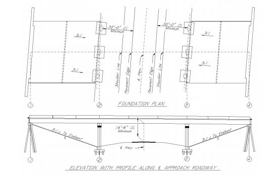
Clearance is usually calculated between the foglines of the road below. This represents the traveled way. Inside the traveled way, the bridge designer must maintain the minimum vertical clearance at all locations. This is usually 16.5 feet in most jurisdictions in the United States. This minimum also applies during all phases of construction. Where falsework is required for cast-in-place construction over live traffic, allowances are usually made in the profile to accommodate falsework depth.
Once the preliminary plan phase is complete, both the client and the bridge designer will be in agreement on the geometric layout of the bridge, the structure type and the pier placement. A revised cost estimate will be provided that will more accurately reflect the cost of the actual bridge to be built. The completed preliminary plan will inform many future phases of design. It is the beginning of the final design. Since the preliminary plan usually includes the plan, elevation and typical section of the bridge, these views are usually incorporated verbatim into the final design plan set. The preliminary plan is used to start geotechnical work, with soil borings being taken at each pier using the pier stations provided by the preliminary plan. Hydraulic design will also begin once the preliminary plan is finalized.
Since the exact foundation type is usually not known at 30%, the preliminary plan usually omits any specific representation of the substructure. Cost estimates will usually aim to be more conservative to account for a more expensive deep foundation, or two separate costs will be provided for both a shallow and deep foundation type.
One of the goals of preliminary design, besides selecting a bridge layout that satisfies all design criteria, is to choose a bridge design to minimize cost. For most engineers, cost is a byproduct of having to do business. As any engineer will tell you, anything is possible – it just costs money. We just aren’t that interested in money – it is boring. If we had wanted to become stockbrokers, we would have.
That said, since bridges are financed by the public sector 99.9% of the time, it is important to be good stewards of taxpayer dollars. In real terms, since the government is almost always skint, this means the cheapest option is almost always the selected option. The cheapest bridge option varies from region to region, which is why you see a large number of a particular type of bridge being used in a particular area. It isn’t that they ran out of ideas – rather it is the idea that turned out to be the cheapest.
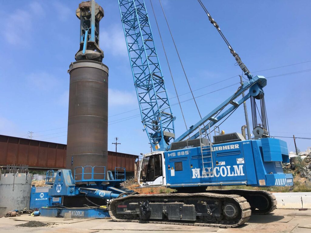
But aside from the use of the same type of bridge over and over, there are other ways to squeeze every dollar out of a particular bridge type. It is a given that the substructure of a bridge is the most expensive portion to construct. Deep foundations use expensive, proprietary equipment usually operated by specialty sub-contractors. Shallow foundations require excavation and shoring. Bridge piers are usually made from concrete, which is cast-in-place and takes time construct. When built over water, in water work and work bridges often drive the cost of the substructure up even further. As a rule, the fewer substructure pieces you have, the cheaper a bridge will be, all other things being equal.
In general, to optimize the design while minimizing cost – reduce your substructure. But there are advantages to reducing substructure beyond cost. Eliminating piers in a waterway will reduce the chance of scour occurring, reduce inspection costs by eliminating underwater inspections and greatly reduce the need for work bridges. Larger hydraulic openings allow more water to flow which can affect flood conditions.
However, going to the extreme with pier reduction will often lead to more expensive bridge superstructure types. Launching girders is typically more expensive than using conventional cranes on a work bridge to set girders. Longer spans may rule out cheaper superstructure types in favor of more expensive ones, such as splice girders or segmental construction.
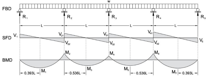
As with all things in our lives – balance is key. A good balanced design is going to be the easiest to construct, the most pleasing to look at and the cheapest to build. For example, a four span continuous plate girder is laid out such that the end spans are about 75% of the length of the two interior spans. Why did the designer lay it out like this? Balance. To most people, an aesthetically pleasing bridge is one where the end spans are shorter than the interior spans. It also provides a more balanced structural design. Since the girder depth is constant, the engineer wants to optimize the use of steel. This is done by making sure the maximum bending moments that the girders have to resist are equal throughout the bridge. From mechanics, in a continuous girder structure, the largest bending moments occur in the end spans. By reducing the length of those spans by about 25% of the interior spans, we get roughly the same maximum bending moments in all four spans, which allows standardization of the girder details and a reduction in cost. Balance – it’s all about balance.
Preliminary bridge design is more of an art than a science. Laying out a roadmap for the bridge designers to follow is an important part of the preliminary engineer’s job. Just like the pencil sketch that led to the beauty of the Mona Lisa, the preliminary plan is the sketch of the final masterpiece. It is the concept, the idea of what could be. This is not meant to discount the many designers that must take the concept and make it a reality – in many cases there are many challenges to overcome during the course of design – but without a great preliminary design, they’ll be lost in the wilderness.
Views: 3885